VCF 9 - NSX VPC Part 2 - distributed Transit Gateway
A short article about VPCs in NSX 9 and VCF 9 Part 2.
2711 Words // ReadTime 12 Minutes, 19 Seconds
2025-06-26 19:00 +0200
Introduction
This is the second article in a series of articles (number of articles unknown) about VPCs in VCF 9. If you are not familiar with VPCs and have not yet come across this topic, I recommend reading Part 1 first. I will not go into all the basics again in this article, as these were already explained in the first article. In this article, I will look at the distributed deployment of VPCs and show how VPCs can also be used without an edge cluster.
Wait, did he really just write VPCs without Edge Clusters?! Sounds good, right?
Let’s go - NSX project
First things first. Since I am using the same VCF 9 installation as in my first article and we already have VPCs in centralized deployment here, I first create a new NSX project. Perhaps I should mention NSX Projects again here. VMware writes in the VCF 9 Guide: A project in NSX is analogous to a tenant. By creating projects, you can isolate security and networking objects across tenants in a single NSX deployment.
I think that description fits quite well. In addition, we can currently only have one transit gateway per project. Since our default tenant (aka default project) has a transit gateway in centralized deployment, I need a new tenant aka project.
To create a new tenant, click on the Project drop-down menu in the NSX GUI and then click on Manage.
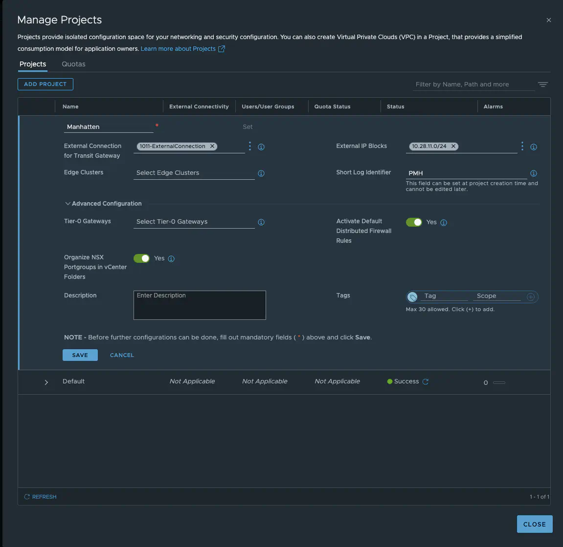
NSX 9 project Manhatten (click to enlarge)
The most important setting besides the name (yes, I recently watched Oppenheimer) is the External Connection. These settings determine whether the transit gateway is distributed or centralized. The External IP Block defines the public VPC network (I explained the different networks in VPCs in Part 1). We have the option of connecting the project to a T0 gateway independently of the transit gateway. However, this is only relevant for non-VPC networks and will not be considered here. The same applies to the option of assigning an edge cluster to the tenant. Since I really want to avoid edges entirely in this article, we will also ignore this option. We also have the option of setting distributed firewall rules directly, which only allows communication within the tenant, but since firewalling will be covered in another article, we will ignore this option and disable it.
We save our Manhattan project and now we have a fresh new tenant.
External Connection - the distributed version
We should take another closer look at the topic of external connections.
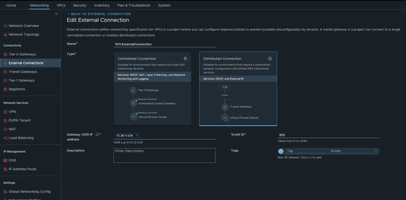
NSX 9 project Manhatten external connection (click to enlarge)
Since we have a distributed connection here, we need a VLAN and a gateway in my physical network. In my lab, it is VLAN 1011 and my Mikrotik Core Router has 10.28.11.1/24. My external IP block also comes from the network area of VLAN 1011, as my physical router has to route to this network.
Let’s build a VPC, or two, or…
Readers of Part 1 should now be quite familiar with all of this.
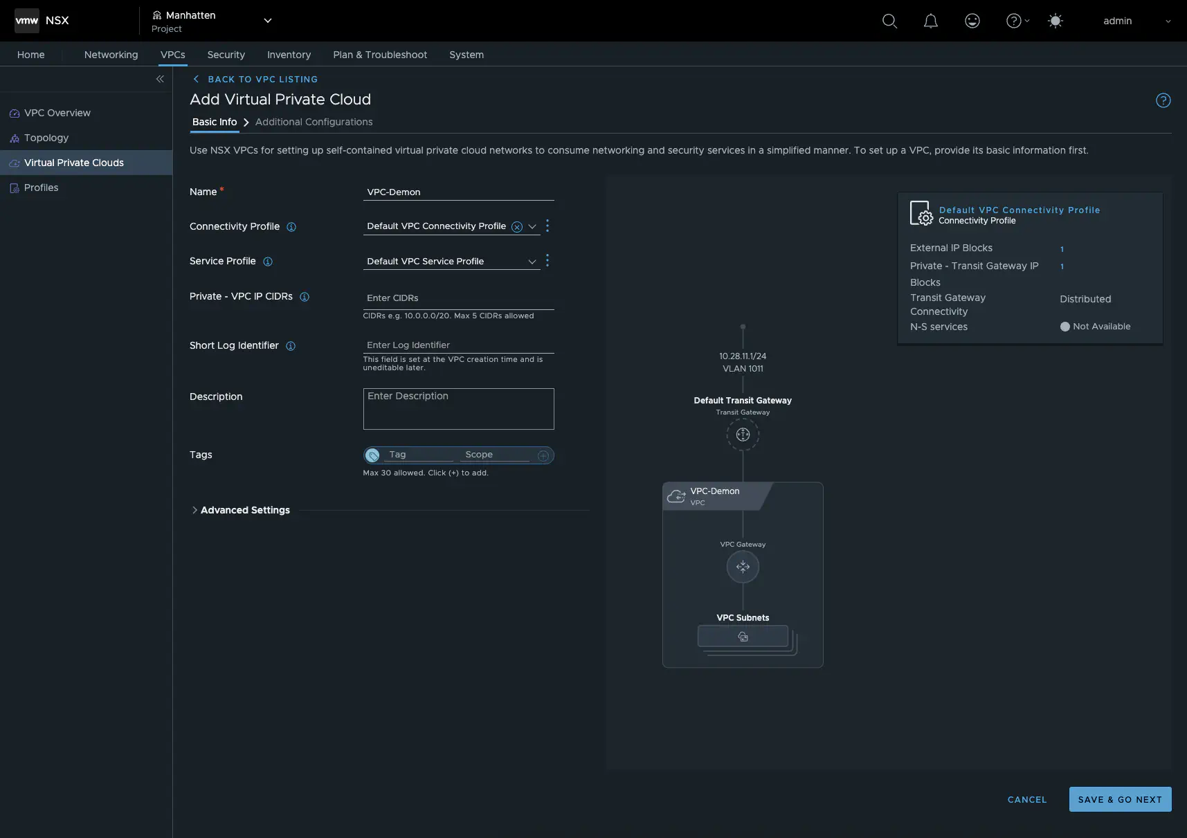
get started with VPC (click to enlarge)
First, we set up our private transit gateway IP block in the VPC Connectivity Profile or create one. Remember, this is an unrouted network, but it must not overlap with the other private VPC networks for all tenants. This network is used to connect VPCs to each other and is an NSX overlay network. Next, I configure the service profile, which is where I can configure a DHCP service for my VPC, and finally I create the private PVC IP CIDRs. As in my other article, this will again be 192.168.5.0/24.
That’s it, our VPC has been created and we can now create our first VPC subnets. I will create a public, a private, and a transit network, each with 16 IPs and DHCP enabled. In addition, I will create the VPC Core in the same way. I hope the Demon Core doesn’t get too close - nudge nudge wink wink.
The tenants’ VPC networks are displayed in vCenter, but they are managed by NSX. This means that they cannot be extended or created via vCenter as in our default project.
Test architecture
I created six test VMs and assigned one VM to each VPC network. For a quick overview, here is a table showing all VMs.
| VM Name | Network Type | Gateway | IP Address |
|---|---|---|---|
| alpine01-demon-private | private | 192.168.5.1/28 | 192.168.5.3 |
| alpine02-demon-transit | transit | 10.28.22.1/28 | 10.28.22.3 |
| alpine03-demon-public | public | 10.28.11.17/28 | 10.28.11.19 |
| alpine04-core-private | private | 192.168.5.1/28 | 192.168.5.3 |
| alpine05-core-transit | transit | 10.28.22.17/28 | 10.28.22.19 |
| alpine06-core-public | public | 10.28.11.33/28 | 10.28.11.35 |
The final VPC structure of the Manhattan tenant looks like this:
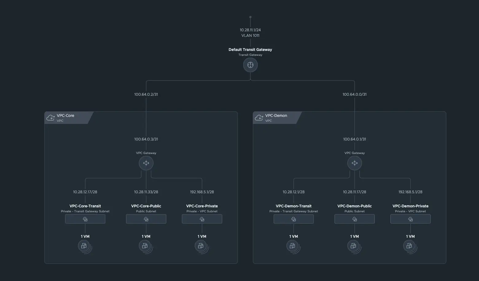
VPCs tenant Manhatten (click to enlarge)
We can also test the interconnectivity between the VPCs from Part 1. The overall network topology looks like this:
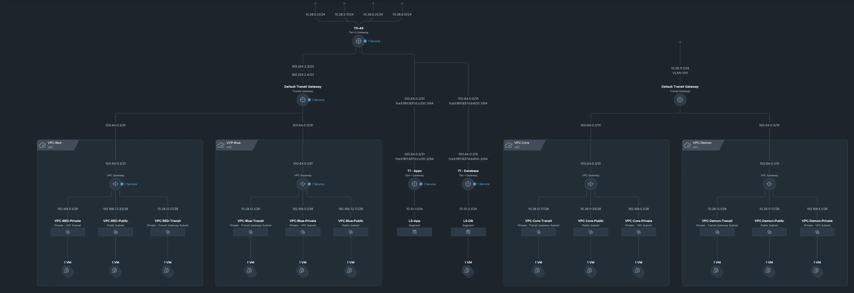
VPCs of all tenants (click to enlarge)
Here are the test VMs from the first article:
| VM Name | Network Type | Gateway | IP Adress |
|---|---|---|---|
| alpine01-blue-private | private | 192.168.5.1/28 | 192.168.5.3 |
| alpine02-blue-transit | transit | 10.28.12.1/28 | 10.28.12.3 |
| alpine03-blue-public | public | 192.168.72.17/28 | 192.168.72.19 |
| alpine04-red-private | private | 192.168.5.1/28 | 192.168.5.4 |
| alpine05-red-transit | transit | 10.28.12.17/28 | 10.28.12.19 |
| alpine06-red-public | public | 192.168.72.33/28 | 192.168.72.35 |
Test scenarios
I will perform certain tests for each VM from VPC-Demon. First, I will test Internet connectivity, then intra-VPC connectivity, i.e., communication with all VMs in VPC-Demon, and finally inter-VPC connectivity, i.e., communication with all VMs in VPC-Core. Finally, I will perform a connectivity test from outside the NSX environment and a connection test to the VMs from VPC-BLUE. I will do all of this with simple ICMP tests. To do this, all firewalls on NSX and the VMs have been disabled. That’s a lot of tests, so let’s get started.
alpine01-demon-private
I will describe the tests using examples. For the other VMSs, I will present the results in a table.
Internet connectivity
In my first test, I want to see where alpine01-demon-private can communicate. The VM was assigned the IP address 192.168.5.3 by DHCP. Since our transit gateway was created in distributed mode, we cannot use auto SNAT and generally have no way of using stateful services. This means that the VM cannot communicate with the internet because the VPC private network is not routed and no SNAT is performed in the public network.
Intra VPC connectivity
Next, I test the connectivity to the alpine02-demon-transit vm. This test is also successful, as the transit VM can also be accessed via the VPC gateway. I also reach alpine03-demon-public vm. This happens fully distributed. Cool.
Inter VPC connectivity
This is where it gets exciting. Basically, I can only access VMs from the same VPC here. If I had stateful SNAT, I could also access the public VMs of other VPCs belonging to other tenants or VMs of other VPCs in the transit network of my own tenant (provided the firewall allows this). Since we do not have NAT, a VM from a private VPC network cannot establish an intra-VPC connection.
External connectivity
The VM cannot be accessed externally. My core router also does not have a route for the 192.168.5.0/28 subnet. Even if my router has a route for this network, a VM in the private VPC network cannot communicate with the outside world. There is a special case, but I will deal with that later.
| Test # | Source | Destination | Connect | NAT | Dist. Routing |
|---|---|---|---|---|---|
| 1 | demon-private | Internet | No | - | - |
| 2 | demon-private | demon-transit | Yes | - | Yes |
| 3 | demon-private | demon-public | Yes | - | Yes |
| 4 | demon-private | core-private | No | - | - |
| 5 | demon-private | core-transit | No | - | - |
| 6 | demon-private | core-public | No | - | - |
| 7 | External | demon-private | No | - | - |
| 8 | demon-private | blue-private | No | - | - |
| 9 | demon-private | blue-transit | No | - | - |
| 10 | demon-private | blue-public | No | - | - |
alpine02-demon-transit
| Test # | Source | Destination | Connect | NAT | Dist. Routing |
|---|---|---|---|---|---|
| 1 | demon-transit | Internet | No | - | - |
| 2 | demon-transit | demon-private | Yes | - | Yes |
| 3 | demon-transit | demon-public | Yes | - | Yes |
| 4 | demon-transit | core-private | No | - | - |
| 5 | demon-transit | core-transit | Yes | - | Yes |
| 6 | demon-transit | core-public | Yes | - | Yes |
| 7 | External | demon-transit | No | - | - |
| 8 | demon-transit | blue-private | No | - | - |
| 9 | demon-transit | blue-transit | No | - | - |
| 10 | demon-transit | blue-public | No | - | - |
alpine03-demon-public
| Test # | Source | Destination | Connect | NAT | Dist. Routing |
|---|---|---|---|---|---|
| 1 | demon-public | Internet | Yes | - | Yes |
| 2 | demon-public | demon-private | Yes | - | Yes |
| 3 | demon-public | demon-transit | Yes | - | Yes |
| 4 | demon-public | core-private | No | - | - |
| 5 | demon-public | core-transit | Yes | - | Yes |
| 6 | demon-public | core-public | Yes | - | Yes |
| 7 | External | demon-public | Yes | - | Yes |
| 8 | demon-public | blue-private | No | - | - |
| 9 | demon-public | blue-transit | No | - | - |
| 10 | demon-public | blue-public | Yes | - | No |
That’s a lot of connections. Why is that? Technically speaking, the VM shoud be located in VLAN 1011. But is that really true? Let’s take a closer look.
The magic of the distributed transit gateway
When we look at a traceflow of the VM alpine03-demon-public, we see that the VM is routing even though I am addressing my physical router.
alpine03-demon-public:~# traceroute 192.168.11.1
traceroute to 192.168.11.1 (192.168.11.1), 30 hops max, 46 byte packets
 1  10.28.11.17 (10.28.11.17)  0.224 ms  0.168 ms  0.048 ms
 2  100.64.0.0 (100.64.0.0)  0.064 ms  0.079 ms  0.038 ms
 3  192.168.11.1 (192.168.11.1)  0.265 ms  0.168 ms  0.188 ms
In NSX, it looks like this:
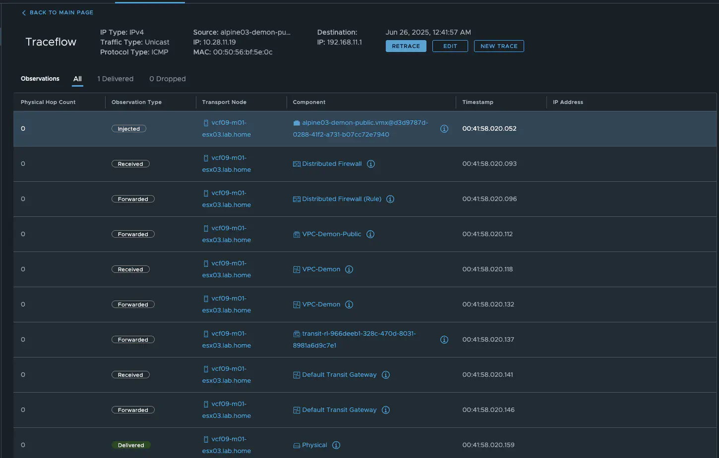
NSX Traceflow (click to enlarge)
Maybe we should take a look at the trace flow from my router.
[admin@ToR.lab.home] > tool/traceroute 10.28.11.19
ADDRESS                          LOSS SENT    LAST     AVG    BEST   WORST STD-DEV STATUS
10.28.11.19                        0%    7   0.6ms     0.5     0.3     0.6     0.1
It appears unusual, as if the VM were directly in the VLAN. As a cross-check from my Mac computer, we also do not see 100.64.0.0 or 10.28.11.17 in the traceroute.
danielkrieger@MBP-DKrieger ~ traceroute 10.28.11.19
traceroute to 10.28.11.19 (10.28.11.19), 64 hops max, 40 byte packets
1 firewall.lab.home (192.168.10.1) 1.076 ms 0.331 ms 0.204 ms
2 192.168.9.2 (192.168.9.2) 0.651 ms 0.357 ms 0.309 ms
3 10.28.11.19 (10.28.11.19) 0.810 ms 1.100 ms 0.482 ms
Wait a minute. What is VMware doing?
From an external perspective, my Mikrotik router can address the VM directly, and I can also see the MAC address of the VM on the switch port of the ESX server in the router’s ARP table. From the outside, it actually looks as if the VM is in VLAN 1011 as normal. However, the VM would then be unable to communicate because if we take a closer look at the VM’s IP address, we can see that it is in a subnet of 10.28.11.16/28 and its default gateway is not .1 (Mikrotik router) but .17.
alpine03-demon-public:~# ip a
2: eth0: <BROADCAST,MULTICAST,UP,LOWER_UP> mtu 1500 qdisc pfifo_fast state UP qlen 1000
    link/ether 00:50:56:bf:5e:0c brd ff:ff:ff:ff:ff:ff
    inet 10.28.11.19/28 scope global eth0
       valid_lft forever preferred_lft forever
    inet6 fe80::250:56ff:febf:5e0c/64 scope link
       valid_lft forever preferred_lft forever

alpine03-demon-public:~# route -e
Kernel IP routing table
Destination     Gateway         Genmask         Flags   MSS Window  irtt Iface
default         10.28.11.17     0.0.0.0         UG        0 0          0 eth0
10.28.11.16     *               255.255.255.240 U         0 0          0 eth0
Another indication that the VM cannot be in a VLAN is the fact that I can route to private VPC networks without without an T0. The VM is therefore in an overlay network.
As we can see in the Traceflow Tool in NSX, the traffic is sent to the Transit Gateway and then directly to the VLAN. Since our transit gateway is distributed, all of this happens on the ESX server on which the VM is currently running. This clarifies the outgoing traffic, but how does the response get back?
Well, I mentioned that my Mikrotik switch knows the MAC address of the VM on the switch port of the ESX server. In addition, my Mikrotik does not know the subnets that NSX creates for the VPCs but the router has a /24 route for the complete Public network.
To ensure that data traffic arrives at the correct ESX, the distributed Transit Gateway running on the ESX hosting the VM responds to ARP requests for the VM, allowing my Mikrotik router to send the data traffic to the correct ESX server. The distributed Transit Gateway will never respond to ARP requests for VMs hosted on a different ESX. The ESX server receives the traffic and sends it directly to the VM.
Insert the “Nice Meme” here.
That was quite a lot, but we’re still not quite done, because there’s also a NAT column in my test table.
External IPs aka reflexive NAT
Similar to centralized deployment, it is possible to expose a VM from a private VPC network. However, since we do not have an edge, this is only possible via reflexive (stateless) NAT. The procedure is the same: we go to the settings of the VPC demon under Additional Configurations and select External IPs. In the dialog, we can only select VMs that have not yet been assigned an external IP and that have a connection in either a transit or private VPC network.
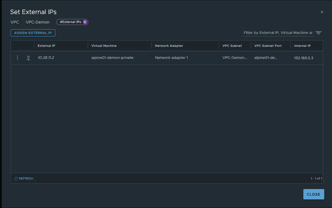
VPC-Demon External IPs(click to enlarge)
As we can see in the screenshot, an IP address from the public VPC network range has been assigned. The VM alpine01-demon-private can be accessed directly via the IP 10.28.11.2 and can also communicate with the Internet via this address. The complete communication is as follows:
| Test # | Source | Destination | Connect | NAT | Dist. Routing |
|---|---|---|---|---|---|
| 1 | demon-private | Internet | Yes | Yes | Yes |
| 2 | demon-private | demon-transit | Yes | No | Yes |
| 3 | demon-private | demon-public | Yes | No | Yes |
| 4 | demon-private | core-private | No | - | - |
| 5 | demon-private | core-transit | No | - | - |
| 6 | demon-private | core-public | Yes | Yes | Yes |
| 7 | External | demon-private | Yes | Yes | Yes |
| 8 | demon-private | blue-private | No | - | - |
| 9 | demon-private | blue-transit | No | - | - |
| 10 | demon-private | blue-public | Yes | Yes | No |
Unlike a VPC with Auto SNAT enabled, it is not possible to communicate from a private VPC network with static NAT to a transit network of another VPC.
With get transport-node external-ip, you can view the external IPs implemented on the ESX host in nsxcli.
vcf09-m01-esx01.lab.home> get transport-node external-ip
Thu Jun 26 2025 UTC 17:08:36.740
                                                  External IP Mapping Table
-----------------------------------------------------------------------------------------------------------------------------
       External IP         Internal IP Discovered       Internal IP Seen            VNI          MAC Address       Port ID
       10.28.11.2                192.168.5.3                 0.0.0.0               69634      00:50:56:bf:5d:b1    67108886

The NSX Reference Design Guide contains traffic flow diagrams for almost all of my tests, for anyone who would like to review everything in detail.
Conclusion
This article shows how VPCs can be operated in NSX 9 in a distributed architecture without any edge clusters. Of particular interest is the functionality of the Distributed Transit Gateway, which transparently mediates between overlay and physical VLAN networks. Despite the absence of edges, many core functions such as routing, public access, and external connections remain fully usable via Reflexive NAT and distributed routing.
The setup allows virtual network functions to be deployed independently of the NSX Edges in a tenant. These could, for example, be provided by a tenant customer themselves. VPCs have become significantly more powerful and exciting than they were in NSX 4.X. This increases flexibility, but also, to be fair, increases complexity. When designing, you have to think more about traffic flow and when traffic is distributed and when it is not. The transit gateway is an exciting new feature and is already familiar from the public cloud sector.
I think in the next VPC article I will deal with the topic of security.
