VCF 9.1 - VNA and VPCs
In this new blog post, I will describe the benefits of virtual network appliances and how to use them.
2971 Words // ReadTime 13 Minutes, 30 Seconds
2026-05-11 00:00 +0200
Introduction
VMware has been cooking up something and has introduced another feature for VPCs and the Transit Gateway. The VNA, or Virtual Network Appliance. But what is it all about, and what can you do with it? Doesn’t this just add even more complexity to an already complex network setup with NSX? Well, as always, the answer is yes and no. What exactly you can do with the VNA, how it’s deployed, why it might make it easier to get started with VPCs and SDN, and what all of this means for people who want to use VKS—I’d like to get to the bottom of all that in today’s article.
But anyway, let’s get started and begin with the simplest part: deploying the VNA.
Deploying a VNA Cluster
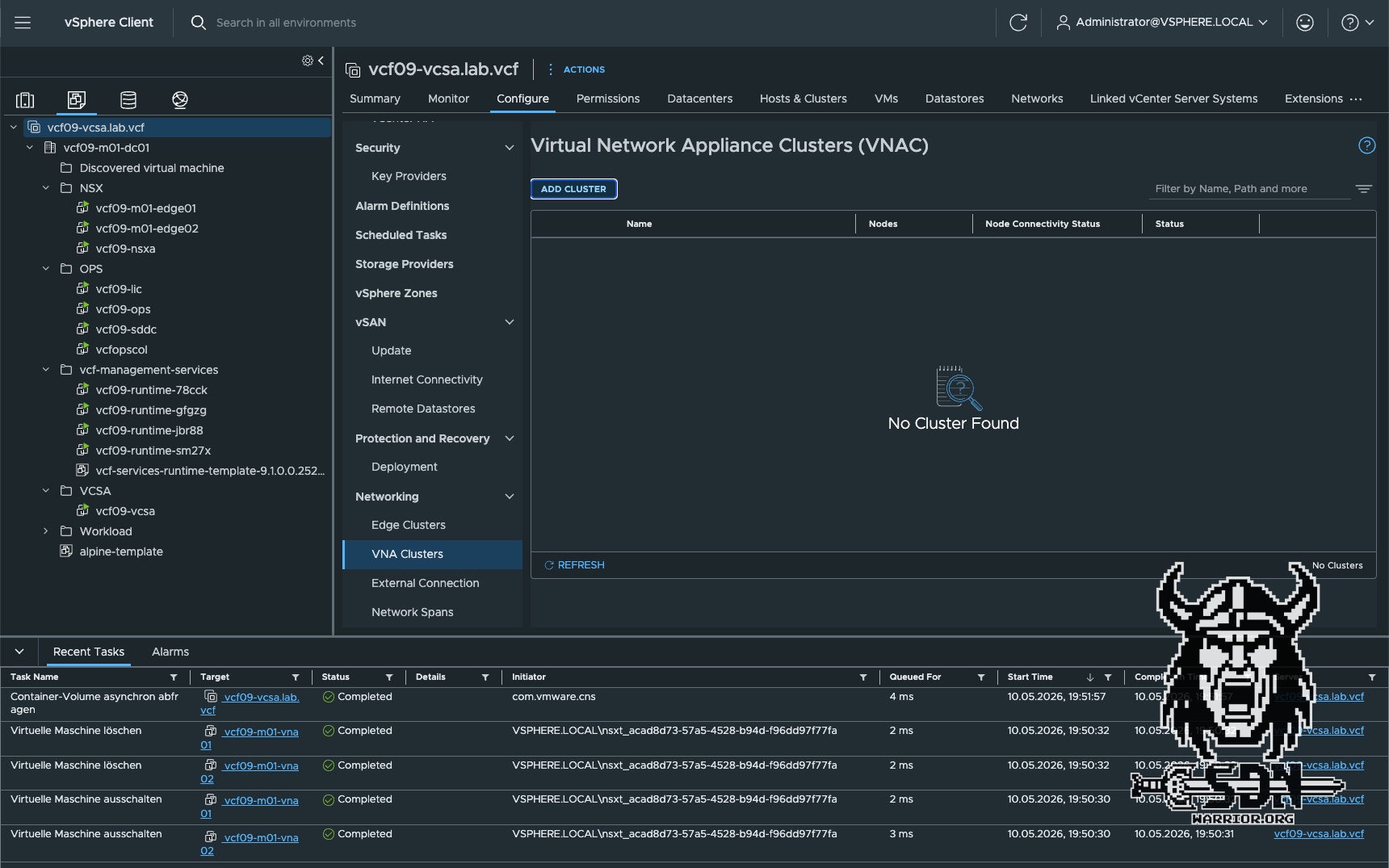
As with Edge clusters, there are two options for VNA as well. Either via vCenter or via NSX. At the end of the day, the process is the same, whether I initiate it via vCenter or via NSX. In NSX, you can create the cluster under System > Fabric > VNA Cluster, and in vCenter, it’s a bit harder to find: click on vCenter, then on Configure, scroll down to Networking, and then click on VNA Clusters. I’ll deploy it via vCenter as an example.
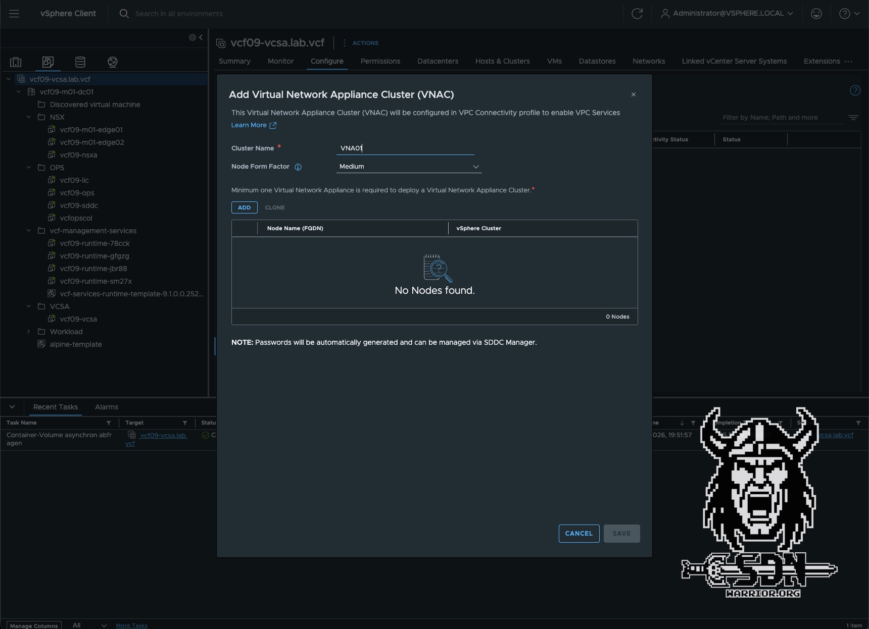
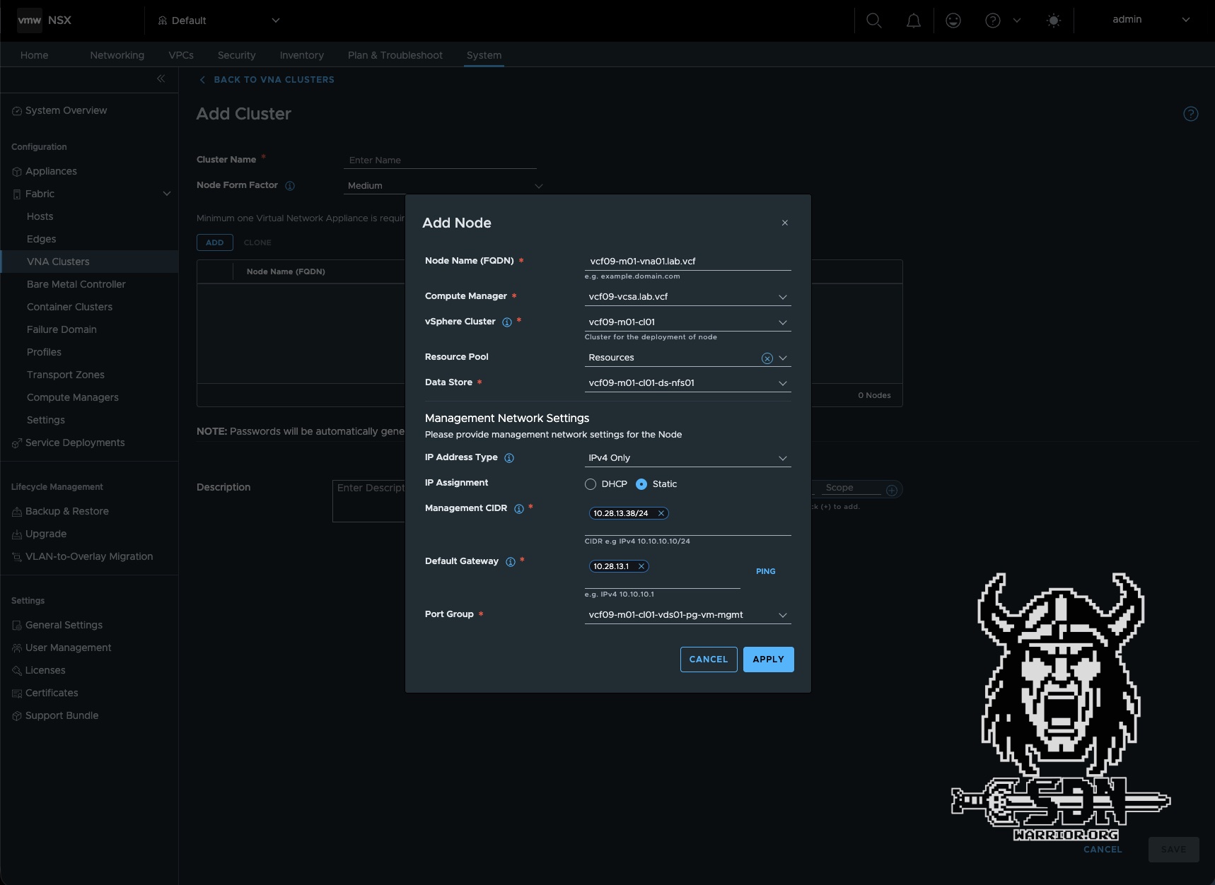
The setup is completed in 4 simple steps. First, you need to create a cluster. To do this, select the cluster name and form factor. These are the same form factors used for an Edge Cluster, by the way. Next, configure the first cluster node by clicking ADD. At least one cluster node is required per cluster, but for high availability (HA) reasons, you should always deploy at least two. Setting up the first cluster node is very similar to setting up an edge node. You need an FQDN, and you must select the appropriate Compute Manager, vSphere cluster, and datastore. For the management network, you can choose between DHCP or static. I generally always use static addresses. Finally, a suitable port group must be selected.
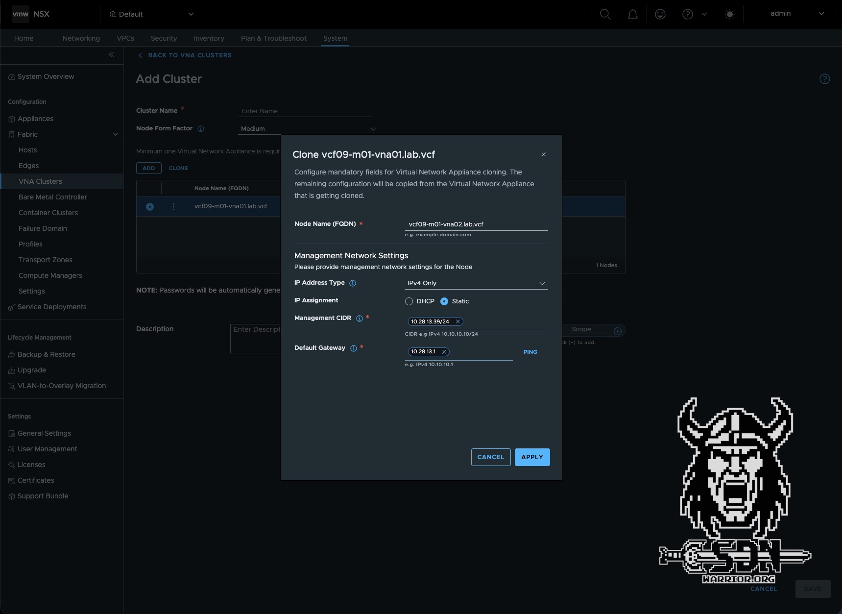
In my setup, I have the VNA management addresses in the VM management network. That’s all there is to it—you don’t need any more information for the first node. You can then simply create the second node from the first using the CLONE button, saving yourself a lot of typing. Here, you just need to specify the delta, i.e., FQDN and IP addresses. After confirmation, the VNA nodes are automatically deployed, and after a short time, they should be visible in vCenter and NSX, with the status showing as Success. The entire setup is now complete.
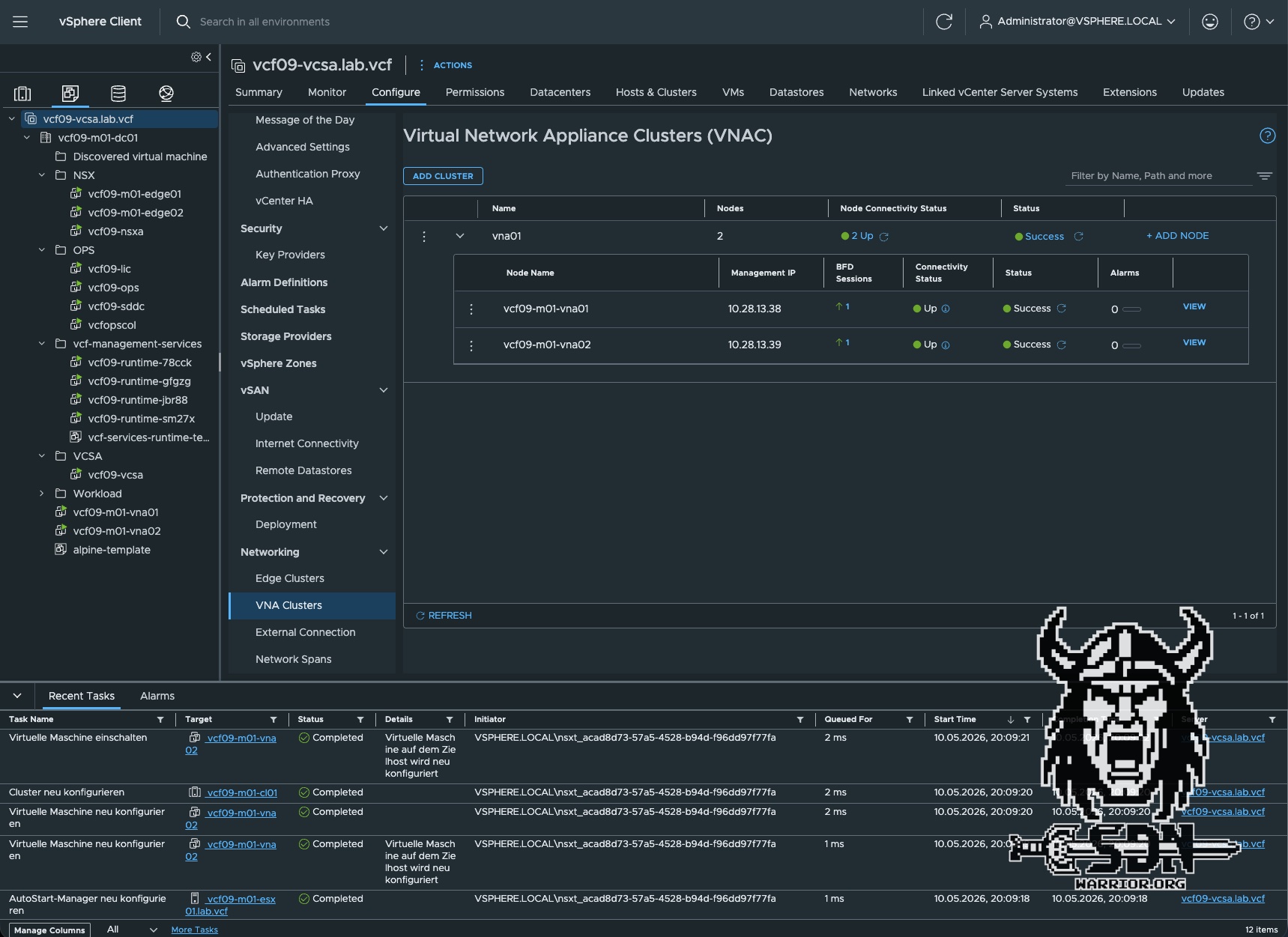
To be honest, that was super easy. But if you take a closer look, there’s actually a bit more going on behind the scenes. That’s because each VNA has been assigned a BFD session. I’ll explain exactly how that works a little later. For now, it’s enough to know that our VNA cluster is up and running.
Choosing the right VNA Size
- Small vCPU: 2 | Memory: 4 GB Use Case: Suitable for Proof of Concept (PoC) and lab environments only.
- Medium vCPU: 4 | Memory: 8 GB Use Case: Suitable for non-critical environments with low volumes of redirected traffic and minimal stateful service processing requirements.
- Large vCPU: 8 | Memory: 32 GB Use Case: Recommended for production environments with high volume of redirected traffic and high stateful service processing requirements.
- Extra Large vCPU: 16 | Memory: 64 GB Use Case: Recommended for environments optimised for NSX Layer 7 load balancer processing requirements.
Using the VNA
Now that our VNA cluster has been successfully deployed, the obvious question is: what do I do with it now? Well, to put it simply, the VNA cluster does not replace an Edge cluster. I cannot run a T0 or T1 router on the VNA cluster. At least for now, it is only possible to use the VNA cluster with a Transit Gateway—and not even with every type of Transit Gateway. The VNA is specifically designed to enable a Distributed Transit Gateway to use Stateful Services; it is also used when implementing VXLAN with VPCs. When the VNA is used for VXLAN integration, it is referred to as a route controller. The VNA then functions fundamentally differently, although the underlying platform remains the same. Route controllers and VNAs for stateful services should not be confused. However, that is not the focus of this article. This topic is still on my roadmap, but I first need to figure out how to create a test scenario with virtual Sonic switches.
To create a VPC with stateful services on a distributed transit gateway, a few steps are required.
New transit gateway
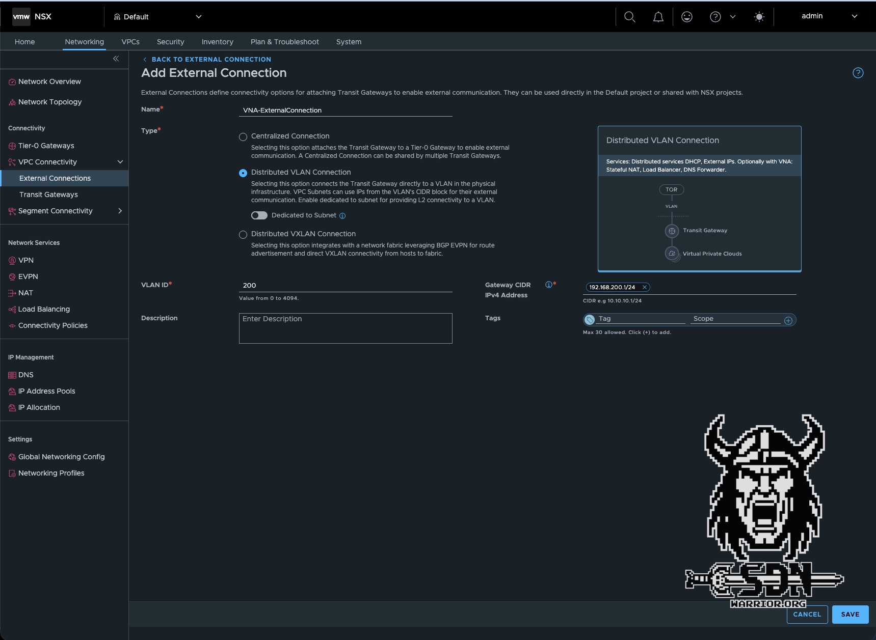
First, you need to create an external connection. In NSX, you can do this under Networking -> VPC Connectivity -> External Connection. To do this, you need a VLAN ID and a physical gateway capable of routing traffic. This external network will later serve as our public subnet within the VPC. In my case, I am using VLAN 200.
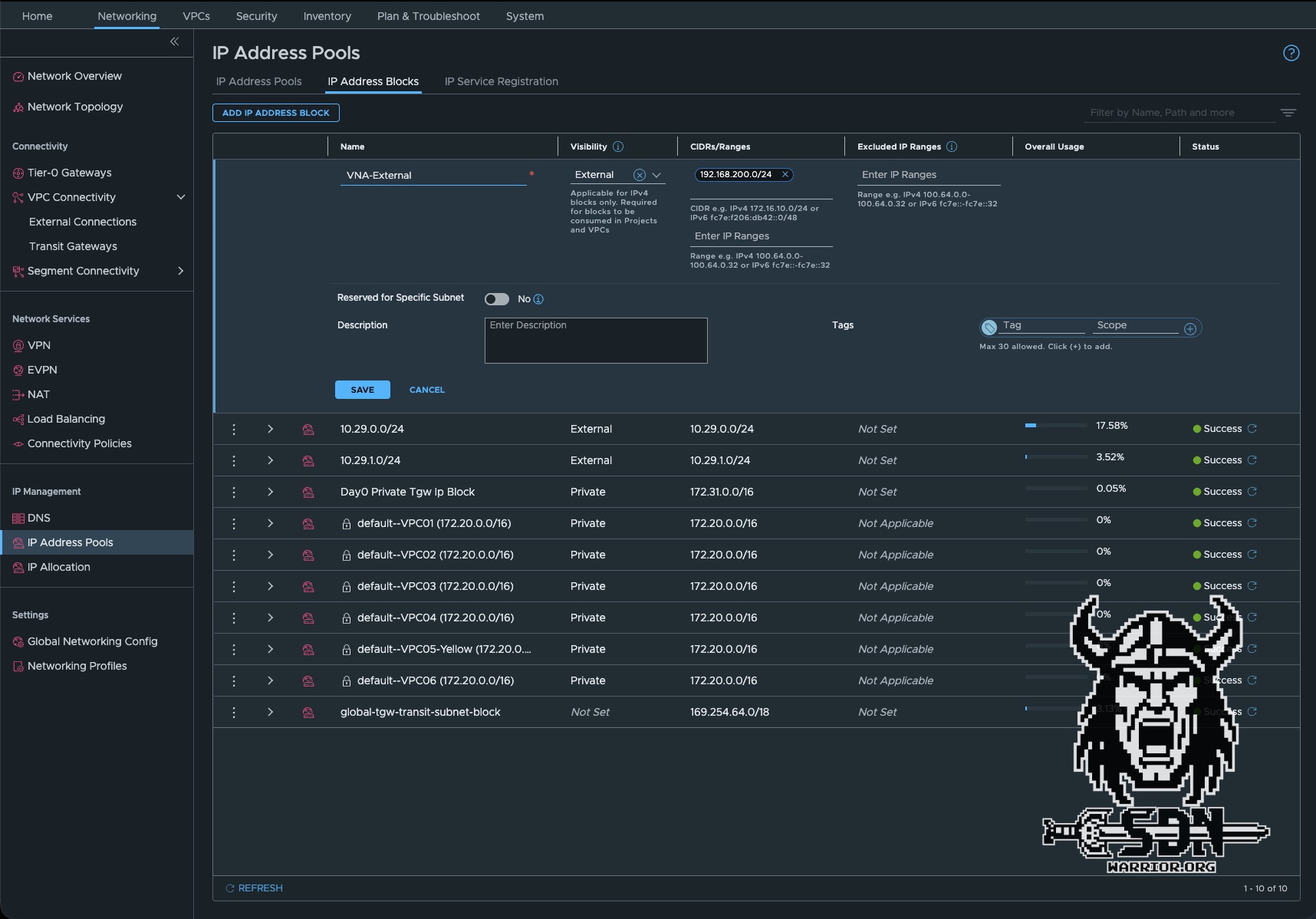
Next, you need to configure an external IP block. This is the IP range from VLAN 200 that can be used. To do this, navigate to Networking -> IP Address Pools -> IP Address Blocks in NSX. It is important to set the visibility to “External”; otherwise, the IP block cannot be used for external connectivity. In my case, I am using the entire 192.168.200.0/24 subnet.
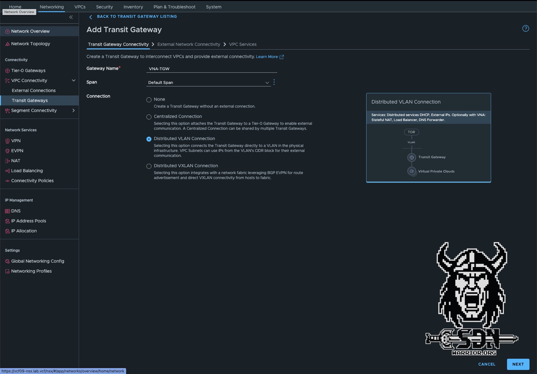
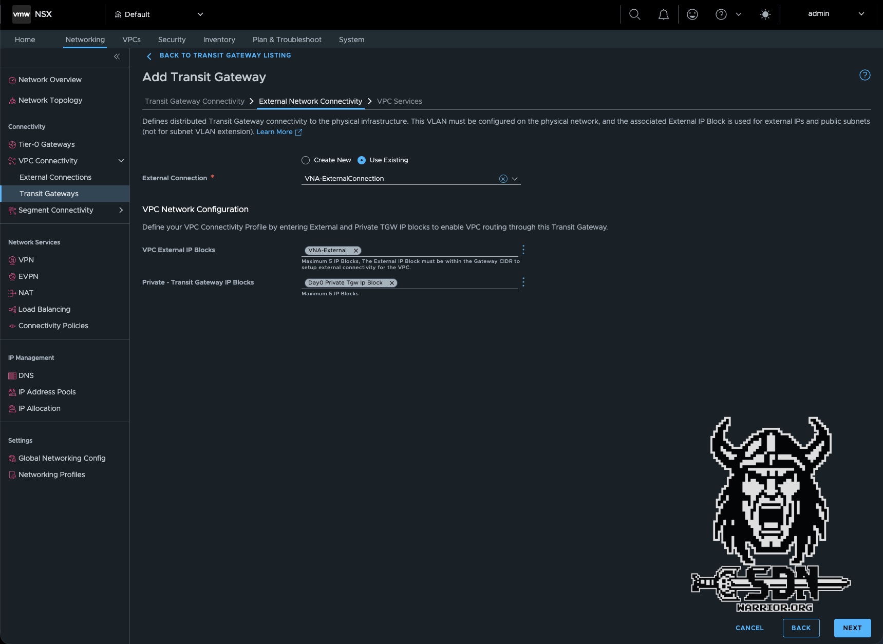
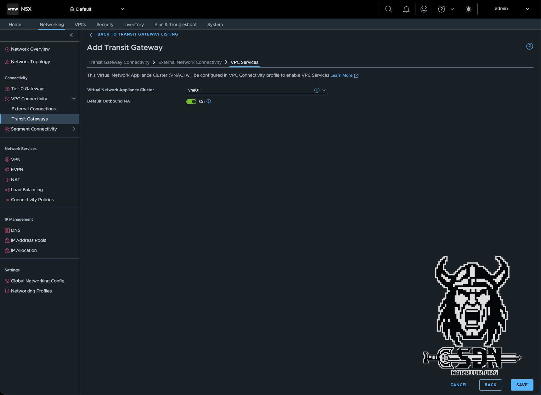
After these two simple steps, you can create the distributed transit gateway. To do this, navigate to Networking -> VPC Connectivity -> Transit Gateways -> ADD TRANSIT GATEWAY and create a new transit gateway. It is important here that you set the connection type to “Distributed VLAN Connection,” since we do not want to use an edge. Next, select the previously created External Connection and the External IP Block. The Private - Transit Gateway IP Block is optional if you want inter-VPC connectivity via the private transit gateway subnet. Here, I simply select the default IP block created by VCF. Then comes what is probably the most important step. Select the VNA cluster and enable default outbound NAT. This is a new feature when creating the distributed transit gateway. All other steps were already available in VCF 9.0.X.
Congratulations! We’ve just created a new transit gateway, and what’s especially cool in VCF 9.1 is that we can create multiple transit gateways within the same NSX project. This means all kinds of configurations are possible. A VPC connectivity profile is automatically created in the background for our transit gateway. This is required when creating the VPC.
New VPC
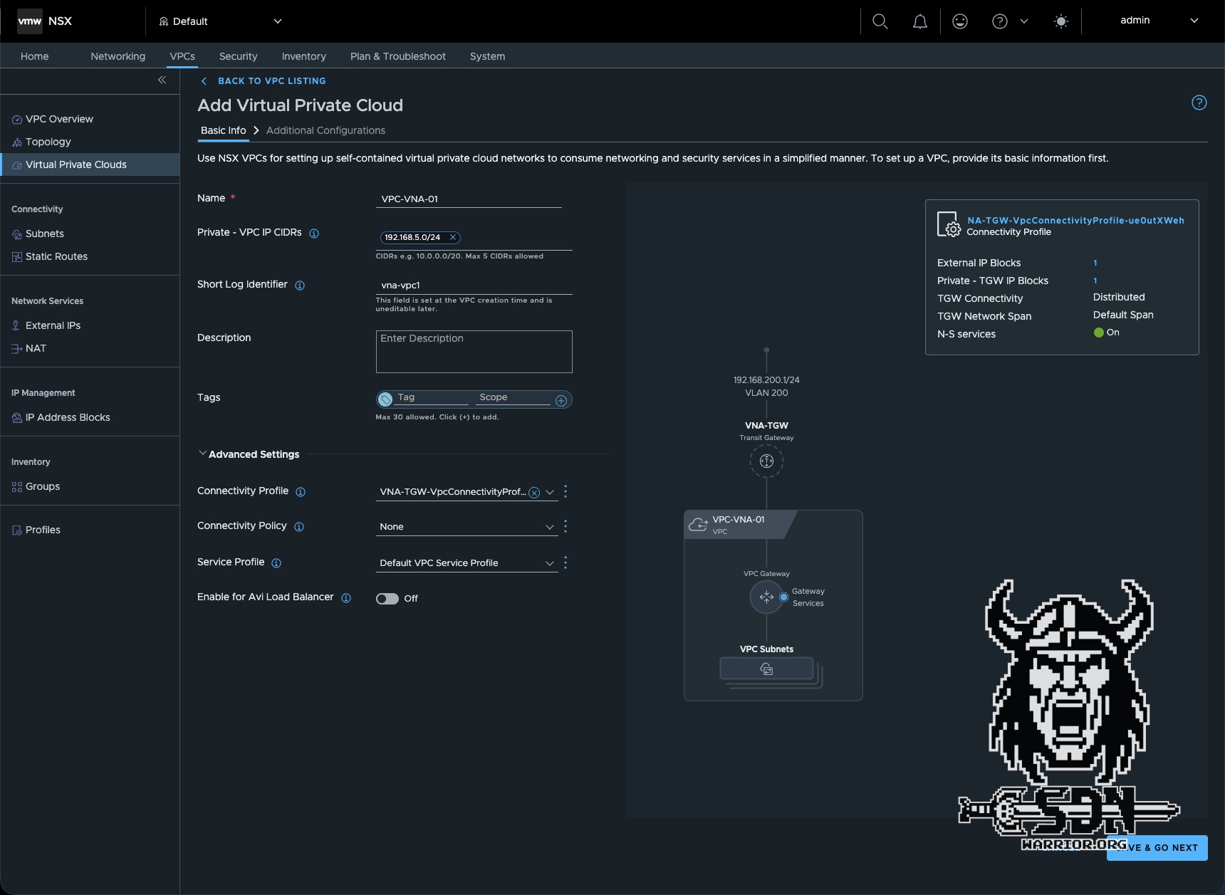
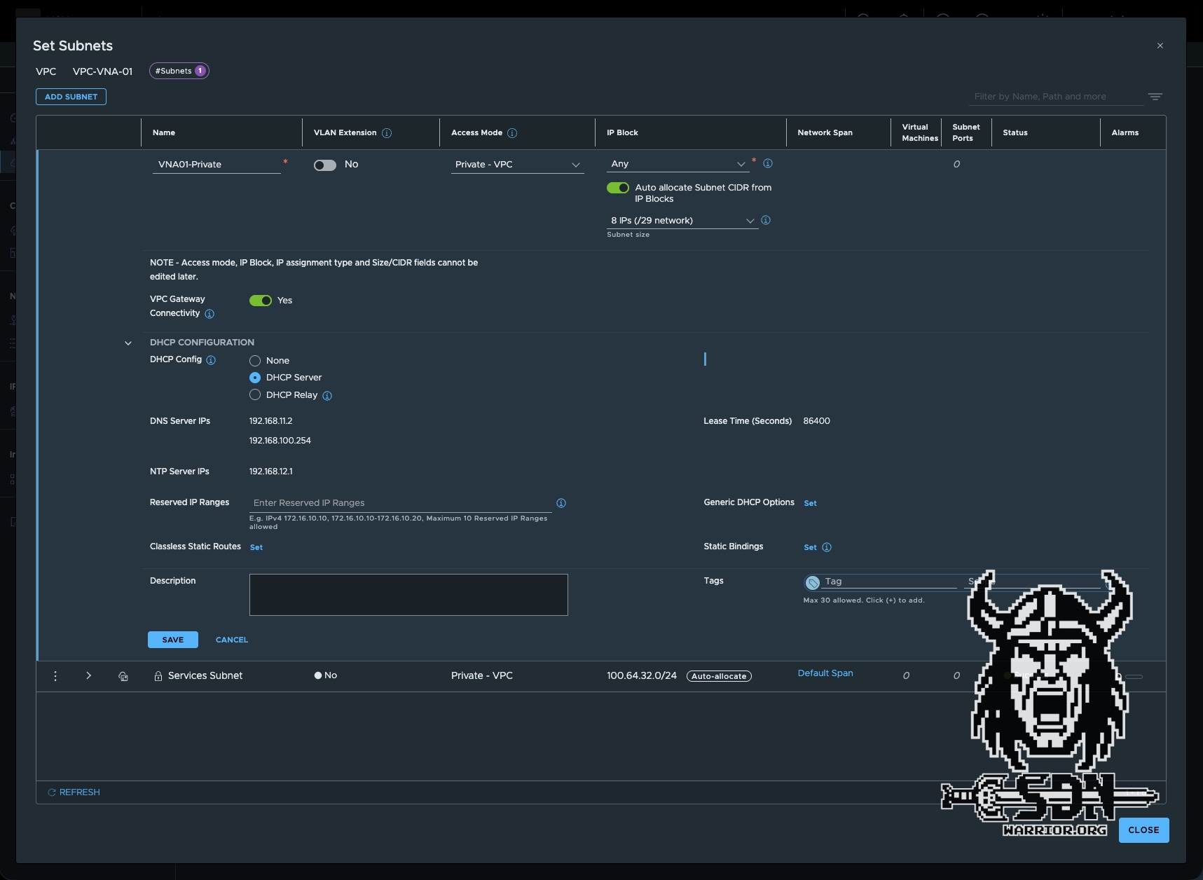
The process of creating a new VPC is essentially the same as in 9.0.X. That’s why I won’t explain it separately. The only important thing here is to select the correct connectivity profile under Advanced Settings. The default connectivity profile is preselected here. The Connectivity Profile ultimately determines which transit gateway my VPC will be connected to. Next, I’ll create a private subnet in my new VPC and clone an Alpine test VM to run my tests.
Testing the new VPC
To perform the first connectivity test, I log in to my newly created Linux VM via the VMware console and check which IP address it was assigned. Since my private subnet is in the 192.168.5.0/24 range and isn’t routed on my network, the VM should have received an IP address from this range via DHCP.
vna-external01:~# ip a
2: eth0: <BROADCAST,MULTICAST,UP,LOWER_UP> mtu 1500 qdisc pfifo_fast state UP qlen 1000
    link/ether 00:50:56:8d:f9:3d brd ff:ff:ff:ff:ff:ff
    inet 192.168.5.3/29 scope global eth0
       valid_lft forever preferred_lft forever
    inet6 fe80::250:56ff:fe8d:f93d/64 scope link
       valid_lft forever preferred_lft forever
vna-external01:~#
Next, I’ll run a simple ping test on Google’s DNS.
vna-external01:~# ping 8.8.8.8
PING 8.8.8.8 (8.8.8.8): 56 data bytes
64 bytes from 8.8.8.8: seq=0 ttl=118 time=7.766 ms
64 bytes from 8.8.8.8: seq=1 ttl=118 time=8.112 ms
64 bytes from 8.8.8.8: seq=2 ttl=118 time=7.458 ms
^C
--- 8.8.8.8 ping statistics ---
3 packets transmitted, 3 packets received, 0% packet loss
round-trip min/avg/max = 7.458/7.778/8.112 ms
How does it all work?
Let’s go into the rabbit hole and take a look at the Traceflow results first.
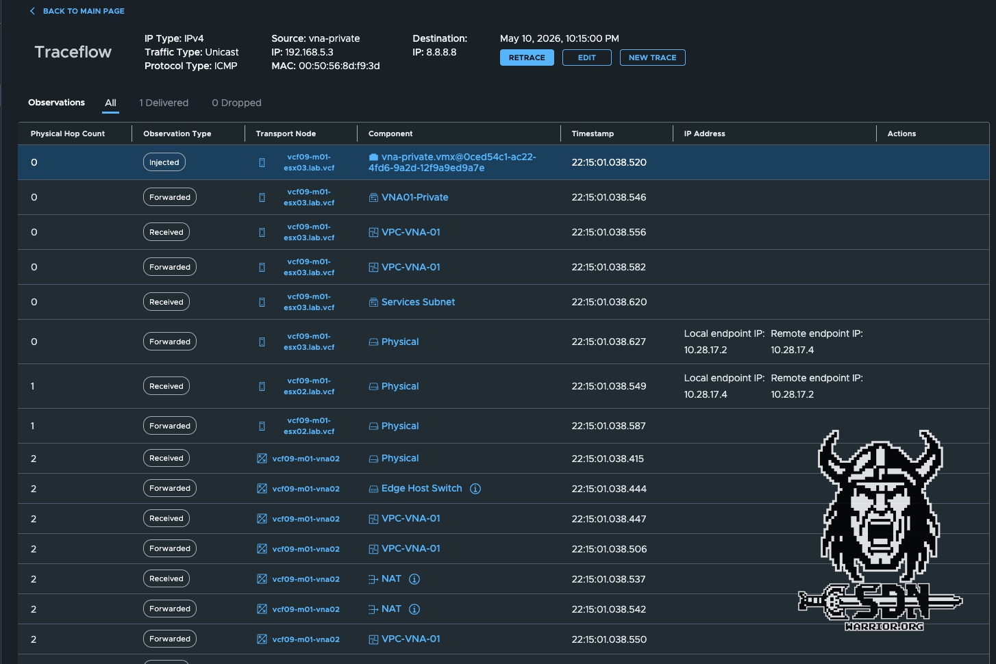
Since the traceflow is too long and unfortunately doesn’t fit in a screenshot, I took the time to write it all out in a table. Okay, to be honest, I just selected everything and told ChatGPT to create a Markdown table and shorten the columns, but there’s no need to make more work for yourself than necessary.
To fully understand Traceflow, you need to know that my test VM is running on ESX03 and my actively used VNA is on ESX02. Additionally—and I haven’t mentioned this yet—every VPC connected to a distributed transit gateway with stateful services has a private service subnet. This is created automatically and cannot be modified. In my case, this is a /24 subnet from the 100.64.0.0/16 range. Unfortunately, the documentation does not specify exactly what this service subnet does at the time of writing this article. So I can only speculate.
| ID | Hop | Observation | Node | Component | IP Address |
|---|---|---|---|---|---|
| T01 | 0 | Injected | ESX03 | vna-private.vmx@0ced54c1-ac22-4fd6-9a2d-12f9a9ed9a7e | |
| T02 | 0 | Forwarded | ESX03 | VNA01-Private | |
| T03 | 0 | Received | ESX03 | VPC-VNA-01 | |
| T04 | 0 | Forwarded | ESX03 | VPC-VNA-01 | |
| T05 | 0 | Received | ESX03 | Services Subnet | |
| T06 | 0 | Forwarded | ESX03 | Physical | Local endpoint IP: 10.28.17.2Remote endpoint IP: 10.28.17.4 |
| T07 | 1 | Received | ESX02 | Physical | Local endpoint IP: 10.28.17.4Remote endpoint IP: 10.28.17.2 |
| T08 | 1 | Forwarded | ESX02 | Physical | |
| T09 | 2 | Received | VNA02 | Physical | |
| T10 | 2 | Forwarded | VNA02 | Edge Host Switch | |
| T11 | 2 | Received | VNA02 | VPC-VNA-01 | |
| T12 | 2 | Forwarded | VNA02 | VPC-VNA-01 | |
| T13 | 2 | Received | VNA02 | NAT | |
| T14 | 2 | Forwarded | VNA02 | NAT | |
| T15 | 2 | Forwarded | VNA02 | VPC-VNA-01 | |
| T16 | 2 | Received | VNA02 | Edge Host Switch | |
| T17 | 2 | Forwarded | VNA02 | Physical | |
| T18 | 3 | Received | ESX02 | Physical | |
| T19 | 3 | Forwarded | ESX02 | Services Subnet | |
| T20 | 3 | Received | ESX02 | VPC-VNA-01 | |
| T21 | 3 | Forwarded | ESX02 | VPC-VNA-01 | |
| T22 | 3 | Forwarded | ESX02 | transit-rl-2d08df91-91ba-4d66-89ec-82a45ad526e6 | View Details |
| T23 | 3 | Received | ESX02 | VNA-TGW | |
| T24 | 3 | Forwarded | ESX02 | VNA-TGW | |
| T25 | 3 | Delivered | ESX02 | Physical |
If you look at the traceflow, you can see that at ID T05, the traffic is routed to the service subnet. The VNA appliance has a service IP in this service network. Here is an example of the configuration for the VNA-02 appliance.
    Interface     : 51c3e094-4818-4293-9070-cbcf488cbdc5
    Ifuid         : 271
    Name          : vpc-svclrp-1034
    Fwd-mode      : IPV4_ONLY
    Mode          : lif
    Port-type     : service
    IP/Mask       : 100.64.32.3/24
    MAC           : 00:50:56:8d:58:78
    VLAN          : 1034
    Access-VLAN   : untagged
    LS port       : 67c06caf-40b1-4559-b18a-43d2df01ad81
    Urpf-mode     : NONE
    DAD-mode      : LOOSE
    RA-mode       : SLAAC_DNS_THROUGH_RA(M=0, O=0)
    Admin         : up
    Op_state      : up
    Enable-mcast  : False
    MTU           : 1500
    arp_proxy     : 192.168.200.2
What’s interesting here is that there is a VRF on the VNA for each VPC, and each VRF has the same service IP but a different ARP proxy IP. This ARP proxy IP is therefore also the default outbound NAT IP for my VPC. But let’s continue in Traceflow
From there, traffic is transmitted normally via a TEP tunnel to the ESX 2 server (T06-T07). Once it reaches the ESX 2 server, the traffic is passed to the VNA via a transit segment (T09-T10). I suspect that child segments are being used here; I can’t say for sure, but it seems likely, especially since the configuration shows that the service interface has a VLAN ID (1034), which makes the whole setup look like tagged VLAN traffic in an overlay network. Please take this statement with a grain of salt.
Now the actual SNAT takes place on the proxy ARP IP address specified in the configuration. (T13-T14) The next interesting step is that the traffic is sent to the hypervisor—not to ESX 3, but to ESX 2, which is also running the VNA appliance. Based purely on the trace flow, as far as I can tell, the traffic actually seem to pass through physical interfaces, from the VNA appliance back to the ESX server. Unfortunately, this is also missing from the documentation and is just my speculation based on the trace flows and tests I’ve conducted. (T15-T19) According to Traceflow, however, there’s a physical hop in between. If in doubt, I’ll have to create a mirror port on my switch and sniff the traffic.
After that, the traffic has reached the VPC gateway again. Since the VPC gateway is distributed, the traffic does not have to go back to ESX 3 (T20–T21) and can be forwarded to the Transit Gateway (T23–T24) and then finally passed into the physical network via the configured VLAN 200 (T25). What a wild ride. By the way, the packet responses flow in exactly the same way, just in reverse order.
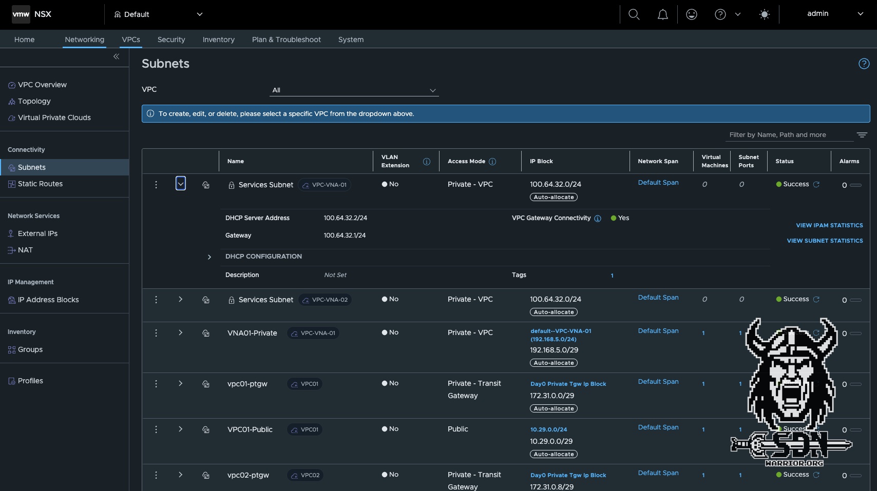
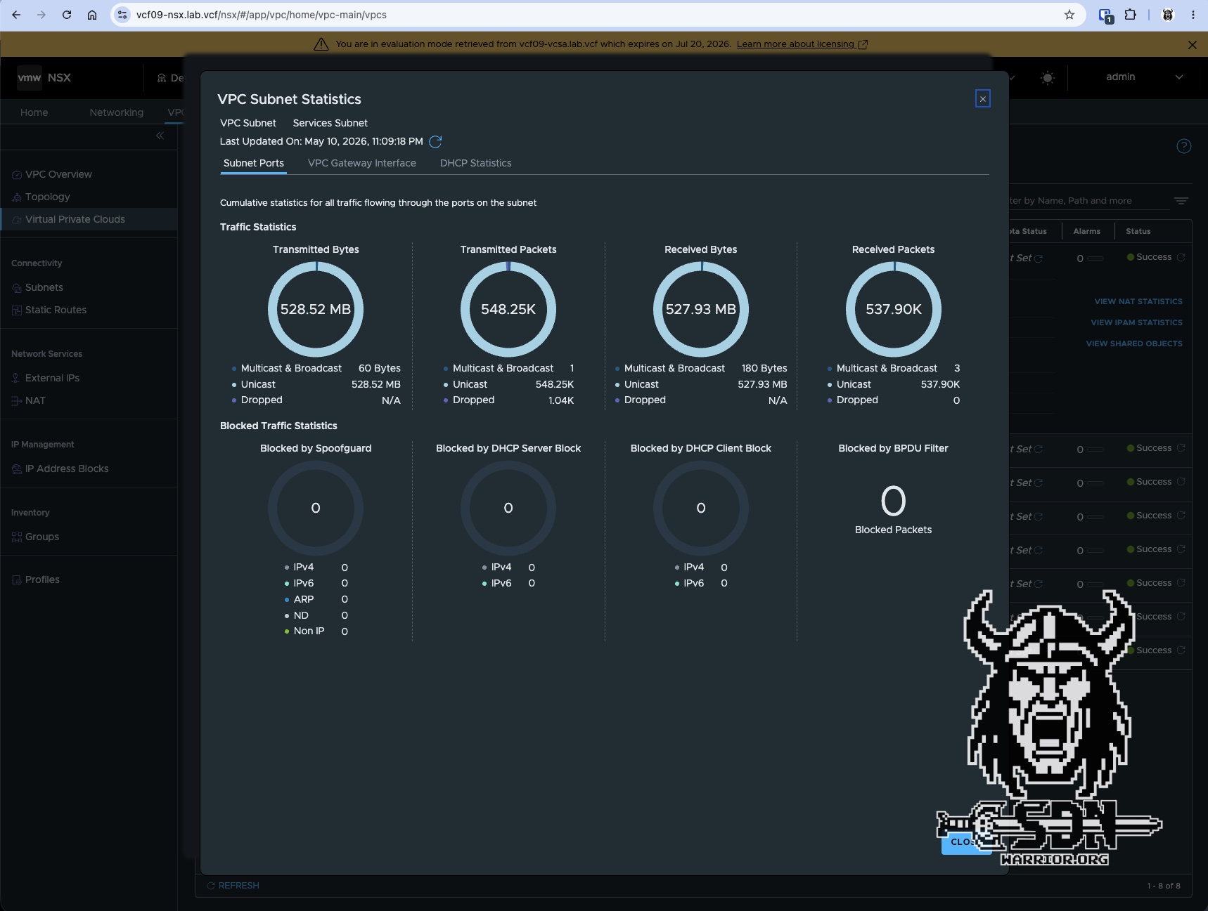
If you look at the statistics for the service interface, you can see that all traffic that needs to be NAT-ed passes through it. To view the subnet statistics, go to VPCs -> Subnets and select the appropriate subnet. It is labeled “Services Subnet,” and when you expand the settings, you will see the VIEW SUBNET STATISTICS button.
Scaling
The Virtual Network Appliance cluster provides a capacity pool and runs one or more service instances for stateful network services. One service instance is configured automatically per VPC when a stateful network service is set up. When two or more Virtual Network Appliance nodes form part of the cluster, the service instance is deployed in active/standby high availability mode; active/active mode is not supported. Each service instance connects to one of the four data plane fastpath interfaces, with multiple instances distributed across all four.
All FastPath interfaces on the VNA are automatically connected to an overlay segment that is created automatically during deployment. To check the status of a VNA appliance, each VNA appliance establishes a BFD session with every other VNA appliance.
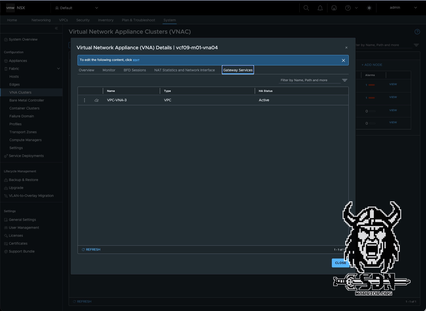
To demonstrate how active services are distributed, I deployed two additional VNA appliances to the cluster. A newly created VPC named VNA-VPC3 was therefore distributed across VNA appliances 3 and 4.


Advantages
The advantages are obvious. Traffic to and from VMs in public VPC networks is routed normally. Here, I don’t have an edge VM that could act as a bottleneck. Integration into existing network infrastructure is incredibly simple; in a pinch, I only need a VLAN and a routed network, yet I don’t have to sacrifice the advantages of private subnets as I would in VCF 9.0.X, and I can use Auto SNAT. You can also assign external IP addresses to VMs in private segments. But here’s what I consider the biggest advantage: I can use VKS with VPCs, which was previously only possible with an Edge cluster and a T0. This way, I get most of the benefits of centralized mode while still being able to easily integrate it into my existing network.
Conclusion
Deploying the VNA clusters is a breeze, and I think it will lead to significantly higher adoption among customers who have so far been resistant to NSX, T0, and dynamic routing protocols. The whole thing actually reminds me a bit of Nutanix’s current VPC implementation or the NSX-V days (which I more or less missed out on). It takes the distributed transit gateway to a higher level and really makes sense in combination with VKS. It definitely reduces complexity, since anyone can usually set up a routable VLAN. Still, there are a few downsides—for example, I’d like to be able to choose which service runs on which VNA appliance, but I suppose there has to be some room for optimization.
