VCF 9.1 - VNA After Dark: Scaling, Spans, and Architecture
In this follow-up article, I take a deeper look at the VNA architecture in VCF 9.1, including placement, relocation, scaling, and network spans.
4562 Words // ReadTime 20 Minutes, 44 Seconds
2026-05-21 22:00 +0200
Introduction
This article cost me a lot of sleep, long nights in the lab, and plenty of coffee. But let’s start from the beginning. I was fortunate enough to have a conversation with a very nice Broadcom employee (Oliver Ziltener) about the VNA. Thank you for your time, for your comments on my first article, and for answering my questions. That really helped me a lot.
If you’re not familiar with the VNA, please read that article first. So let’s not beat around the bush—let’s dive right into the rabbit hole.
VNA Architecture
When I wrote the first article, I was still relying on information from the beta, but now I have a much better understanding of the VNA Appliance’s architecture. So I’ll start by covering the general overview. Important: In this article, I am again focusing solely on the VNA for stateful services, not on the VNA as a route controller.
As described in the first article, the VNA is essentially based on an NSX Edge appliance, although its functionality has been significantly modified. The VNA appliance has four Fastpath interfaces, each of which is connected to an N-VDS GENEVE trunk. Unlike edges, these N-VDSs are not configurable as they are all pre-defined. Each Fastpath interface is automatically connected to the parent NSX overlay segment, which is created specifically for the VNA Cluster. If you have more than one VNA cluster, an additional parent overlay segment is deployed in NSX for each VNA cluster. These are read-only and cannot be edited.
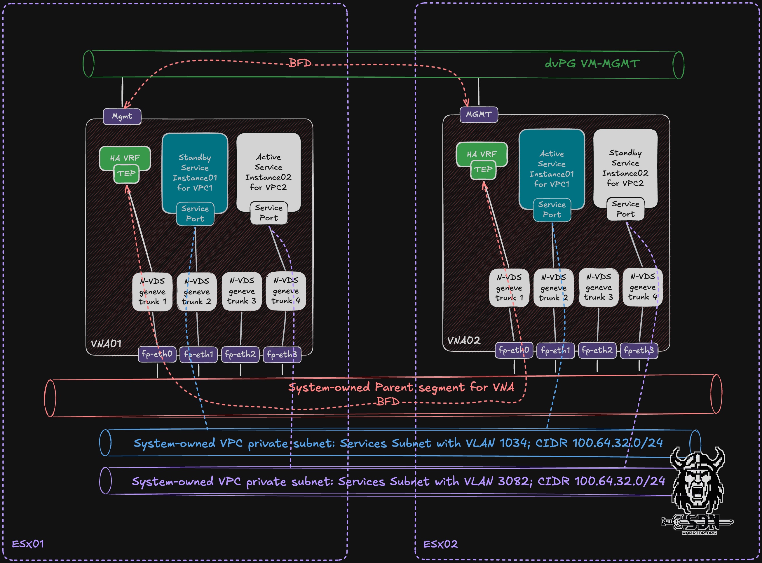
The parent segment serves two purposes: first, it establishes the BFD session between each HA VRF on the VNA appliances via fp-eth0, and second, it distributes traffic from the VPC service subnets (more on that later).
Additionally, another BFD session is established via the management interface of the VNA appliances using a standard distributed switch port group. Since an overlay segment depends on the NSX TEP network, this ensures that there is an “independent” second path to check the status of the VNA cluster.
When creating a VPC, the system automatically determines which VNA appliance from the cluster will host the active service instance and which will host the standby service instance for the VPC. In addition, a fast path interface is automatically selected. This assignment is initially fixed and cannot be changed via the UI. In my diagram, VPC1 Active runs on VNA02 via fast path interface 1, and the standby instance is on VNA01, also via fast path interface 1. For VPC2, it’s exactly the opposite: my active instance is on VNA01 via fast path interface 3, and the passive instance is on VNA02. This means the VNA cluster can be active/active from an overall cluster utilization perspective, because different VPC service instances can be active on different VNAs. However, each individual VPC service instance still follows an active/standby model.
Service Segments
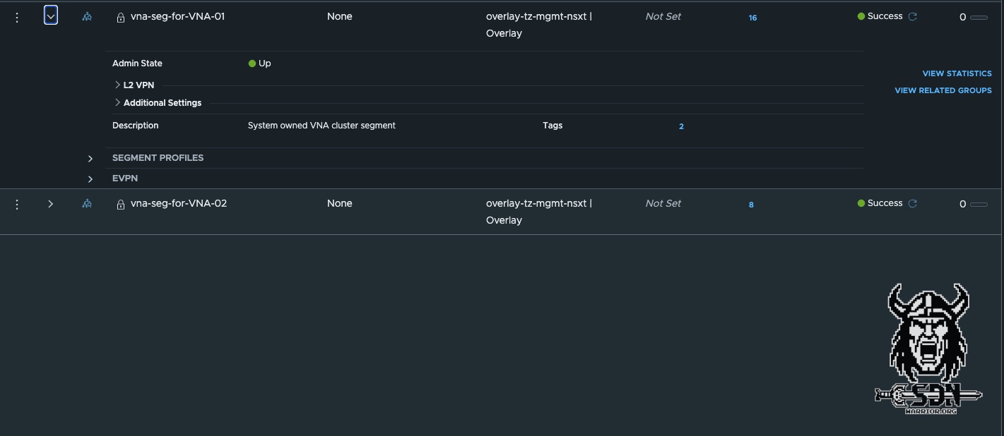
The service segment (system owned VPC private subnet) is what is known as a child segment in NSX, which is simply an overlay segment connected to a parent overlay segment via a child port. This child port extracts traffic for a specific VLAN from the parent segment and forwards it to the child segment. The parent segment is used only to transport the tagged packets. This design is what makes the VNA possible in the first place.
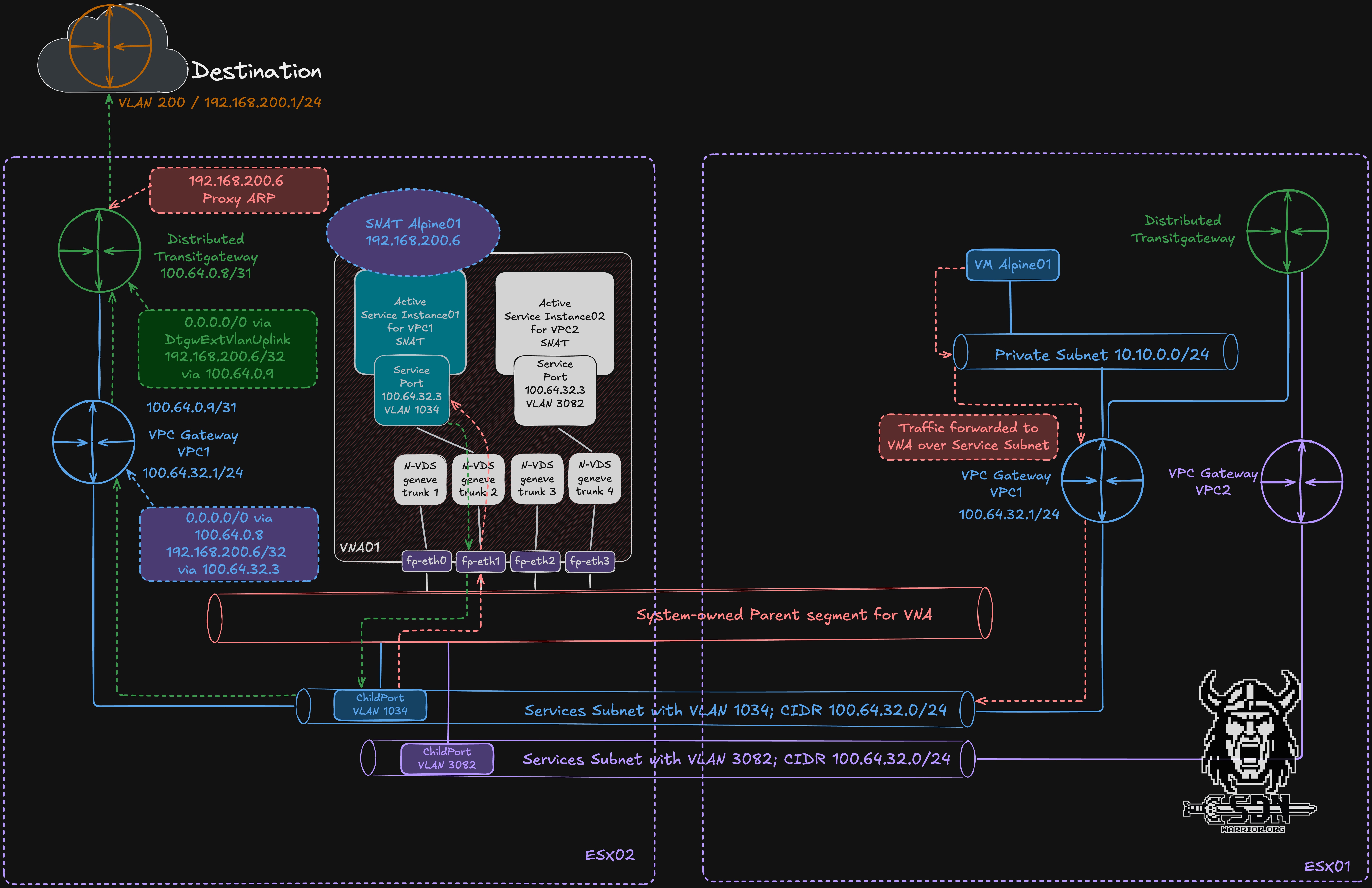
My diagram clearly illustrates the actual egress traffic flow. Traffic from the Alpine test VM destined for the internet is first sent to the private segment and from there to the VPC gateway for VPC1. Like the transit gateway, the VPC gateway is implemented in a distributed manner, meaning it exists on every transport node. Via the VPC gateway, the traffic is redirected to the service subnet of the VPC and sent there to the service port of the active service instance for VPC01. Each service instance always has the same IP address but resides in different VLANs and is thus isolated. Since the active service instance is running on a VNA on a different ESX host, the traffic is sent to the other ESX host via the parent segment. This happens in the usual way, as with any overlay network, via the TEP network between the ESX servers. Upon arriving at ESX Server 2, the child port extracts the VLAN-tagged traffic from the parent segment and forwards it into the corresponding child overlay segment to the active service instance for VPC01. After SNAT has been performed on the active service instance, the packet does not have to return to the original ESX host just to continue its north-south path. Instead, forwarding continues from the transport node where the active service instance is currently running. From the VPC Gateway, the traffic goes to the Transit Gateway and then into our Public VLAN, where the packets are handed over to the physical network. The public VLAN must be a VLAN within the physical infrastructure, and SNAT IP addresses and smaller subnets for VPC public networks are automatically provisioned from this network.
Why do I need this parent interface structure? Can’t I just use multiple overlay segments for the VNA?
The answer is simple—scaling. A VM can have a maximum of 10 network interfaces; technically, it’s not possible to have more than that at this time. But if I want to provide stateful services to more than 9 VPCs, I run into a bottleneck and don’t have enough interfaces. In addition, the VNA only has 4 fast-path interfaces capable of processing traffic quickly. That’s why each fast-path interface is connected to an N-VDS trunk port, so I need a way to use VLANs. I therefore work around this limitation by simply sending my traffic tagged to the parent interface, and the child ports then route the traffic to the actual child segments. A simple and elegant solution.
Relocation and placement
The VNA supports three types of relocation: automatic relocation, Standby relocation and manual relocation triggered via API. But before I go into detail about relocation, I need to explain the placement of VPCs.
It’s relatively simple: when creating the VPC, a VNA appliance is selected to host the VPC’s active service instance and another to host the standby instance (as long as there are at least 2 VNA appliances in the cluster). The user has no control over which VNA appliance is used. The system attempts to select a suitable VNA appliance based on the VNA’s load. Note that VNA load does not necessarily refer to throughput values but rather to how many VPCs are already mapped to the VNA appliance. If you have a VNA cluster consisting of two VNAs, it is possible that one VNA will host all active VPC instances. For most use cases, this automatic distribution is perfectly sufficient. However, users aren’t completely powerless, because with the power of the API, we can of course customize the behavior.
We have two options here: we can trigger a reallocation for a VPC and hope that it will be distributed more effectively, or we can specifically assign two preferred VNAs.
The following API call is required for a simple relocation.
https:/<NSX Manager IP>/policy/api/v1/infra/gateways/action/reallocate
In addition, a JSON body must be included. It is important to include the VPC API path. You can easily copy this from the NSX UI.
{
  "gateway_path" : "/orgs/default/projects/default/vpcs/DTGW-VPC05"
}
The relocation usually happens instantly, but the API only returns a 200 OK response. You’ll see the results in the NSX user interface after a little while, so grab a cup of coffee and sit back and relax.
The next option, however, might be the more interesting one, since I can also specify preferences regarding where the services should be migrated. The basic request is the same; you just need to adjust the JSON body.
{

 "gateway_path" : "/orgs/default/projects/default/vpcs/DTGW-VPC05",
 "preferred_edge_paths":
 [
    "/infra/sites/default/enforcement-points/default/virtual-network-appliance-clusters/VNA-01/virtual-network-appliances/vcf09-m01-vna01",
    "/infra/sites/default/enforcement-points/default/virtual-network-appliance-clusters/VNA-01/virtual-network-appliances/vcf09-m01-vna02"
 ]
}
However, the API call does not allow you to specify which VNA the active service component is running on. This is also selected automatically. By the way, if you don’t want to wait for NSX’s slow UI, you can also connect to the VNA via SSH and use the command get gateways. The result will look like this:
vcf09-m01-vna04> get gateways
Tue May 19 2026 UTC 21:52:59.291
Gateway
UUID                                   VRF    Gateway-ID   Name                              Type                        Ports   Neighbors
eccd1cc8-f11e-49a1-9268-3a394298352e   1      1026         SR-DTGW-VPC01                     SERVICE_ROUTER_TIER1        4       1/50000
875c4556-ba10-427d-8135-ed2b04b98df7   2      2054         SR-DTGW-VPC02                     SERVICE_ROUTER_TIER1        4       0/50000
736a80e3-23f6-5a2d-81d6-bbefb2786666   4      0                                              TUNNEL                      3       3/5000
76b971e4-e29a-4bdc-bfb6-38090bf8ee12   5      2059         SR-DTGW-VPC04                     SERVICE_ROUTER_TIER1        4       1/50000
23f4d581-62a6-41e6-84c1-3501953af6aa   6      2056         SR-DTGW-VPC03                     SERVICE_ROUTER_TIER1        4       0/50000
And the corresponding option in the NSX UI.
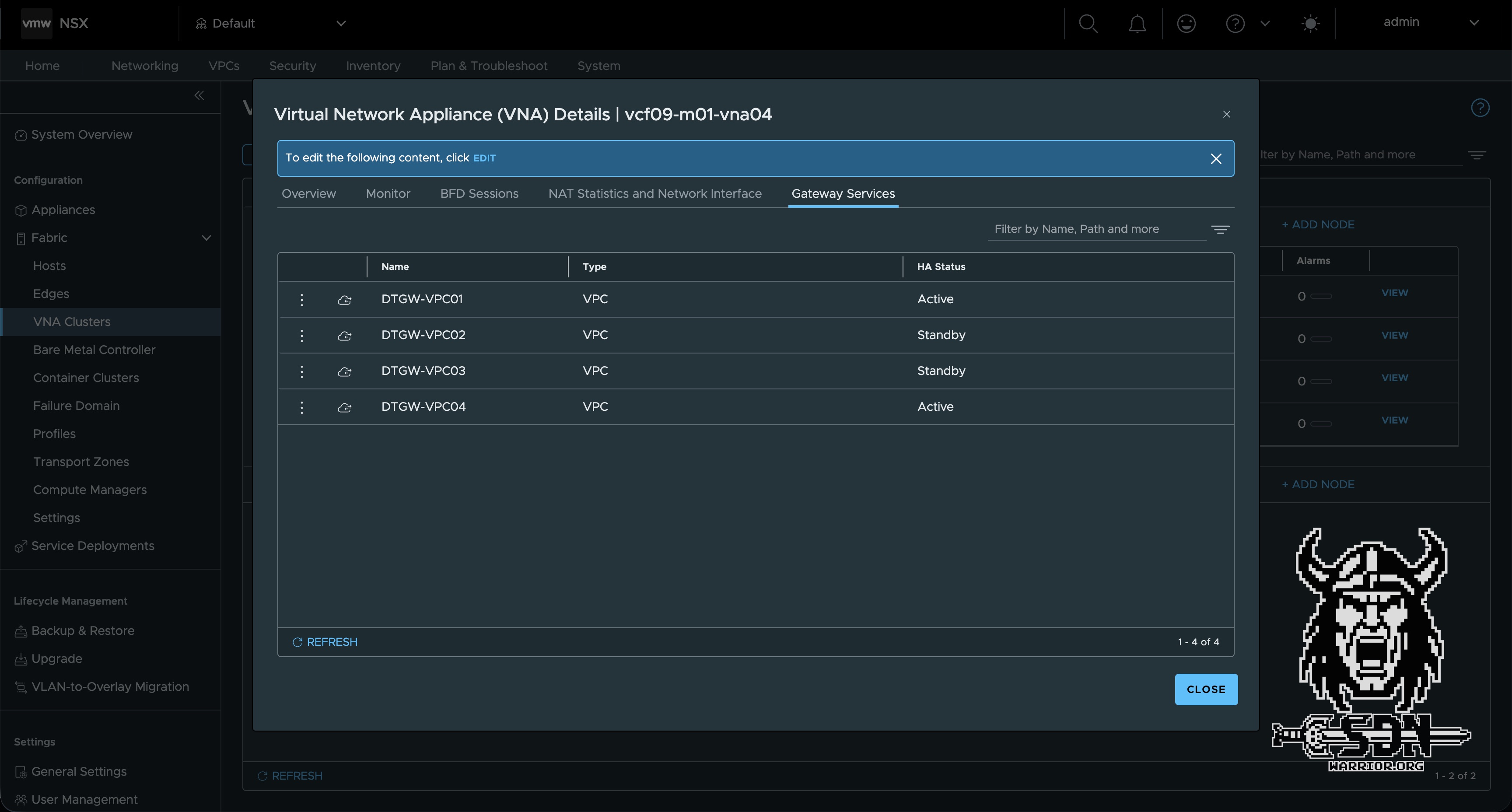
The attentive reader will have noticed by now that all VPCs are displayed as T1 service routers in the VNA, and that the active service instances have a “1” in the ‘Neighbors’ column, while the passive ones have a “0.” This allows you to quickly check the status of the service instances via the CLI. Now I just need to explain auto-relocation, and hopefully it will all make sense.
Automatic relocation is triggered when, while adding services (such as an L7 load balancer), resources are exhausted and the capacity of the current node pair is exceeded. This is checked every time a new service or VPC is created and is performed if necessary. Of course, this requires sufficient capacity within the cluster. The cluster does not scale out dynamically.
To better explain (auto) standby-relocation, let’s consider a VNA cluster consisting of at least three VNAs. I have created a VPC, and for this VPC, an active service instance is created on VNA1 and a passive one on VNA2. In this scenario, VNA3 remains empty. If, for any reason, the first VNA appliance fails—that is, the appliance hosting my active service instance for VPC 1—then two things will happen.
- First, thanks to BFD, the VNA will perform a very fast failover; the default settings here are 500 ms for hello, and if 6 hello packets are lost, the VNA is declared dead.
- And second, after 30 minutes, the standby relocation is executed. In simple terms, this means that if VNA1 is not operational again within 30 minutes, a new VNA from the cluster (if available) will automatically be selected as the new standby service instance. This ensures that full HA capacity is restored after 30 minutes.
The relocation is conceptually similar to the T1-SR relocation on the NSX-Edge, but is handled fully automatically for the VNA.
In my example, after VNA1 has been successfully restored, the active service instance is not moved to VNA1 but remains exactly where it is assigned. In a 2-node cluster, this isn’t a major issue, but in a 3- or 4-node cluster, it can certainly lead to occasional overload—and this is where our API call comes into play. In a highly dynamic environment—for example, when using VKS and VPCs are constantly being created and deleted—this behavior is not a major issue and self-regulates, since the placement is re-selected every time a VPC is created. In a static environment optimized for performance, manual intervention may be advisable. However, there is no blanket statement on this, and it is all the more important to understand how the features work. And that brings us perfectly to my next topic.
Scaling and Sizing
Let’s talk briefly about scaling. In my first article, I touched briefly on the topic of sizing. That might have been a bit brief. There are the “T-shirt sizes” familiar from Edge VMs, but VNA works a little differently. I’ll list the T-shirt sizes again anyway:
- Small vCPU: 2 | Memory: 4 GB Use Case: Suitable for Proof of Concept (PoC) and lab environments only.
- Medium vCPU: 4 | Memory: 8 GB Use Case: Suitable for non-critical environments with low volumes of redirected traffic and minimal stateful service processing requirements.
- Large vCPU: 8 | Memory: 32 GB Use Case: Recommended for production environments with high volume of redirected traffic and high stateful service processing requirements.
- Extra Large vCPU: 16 | Memory: 64 GB Use Case: Recommended for environments optimised for NSX Layer 7 load balancer processing requirements.
The important point to note is that a VNA appliance can use a maximum of four vCPUs for datapath processing. This differs from a standard NSX Edge, where the number of usable datapath vCPUs can exceed 4, depending on the form factor and configuration.
From a datapath throughput perspective, an Extra Large VNA does not necessarily offer any additional benefits over a Large VNA if the datapath is already limited to four vCPUs. However, the extra-large form factor can still be relevant for characteristics such as a larger number of L7 load balancer instances or higher memory requirements. If the main use case is stateful services such as SNAT — which will probably be the most common use case for many VNA deployments — a Large VNA is usually the more reasonable choice for production.
In addition to vCPU sizing, the fastpath interfaces are important for performance planning. Each VNA has four fastpath interfaces, and each VPC service instance is assigned to one of these interfaces when the VPC is created. For a design that is optimized for maximum per-VPC datapath performance, I would treat the number of usable fastpath interfaces on a surviving VNA as the practical planning limit.
This distinction is important in a two-node VNA cluster. From a steady-state perspective alone, one could consider eight high-performance VPCs, with four active service instances on VNA01 and four on VNA02. However, this assumes perfect placement control and that no failures will occur. In reality, active placement is selected automatically and it is not currently possible to explicitly define which VNA should host the active service instance for a given VPC.
The second important point is the failover behaviour. As preemptive failback is not supported, service instances will not automatically return to their original VNA after a failed appliance has recovered. In the worst-case scenario, after a failover, all active service instances could end up running on a single VNA. For example, if eight high-performance VPCs were planned for a two-node cluster, the surviving VNA would need to handle all eight active service instances. With only four fastpath interfaces available, at least two VPCs would need to share the same fastpath interface.
For this reason, my conservative planning target for a two-node Large VNA cluster optimised for maximum per-VPC performance would be four high-performance VPCs at most. This assumes that all four fast-path interfaces are usable, and that the design will remain clean after a failover.
This is not a hard scalability limit. It is a design assumption based on performance. In mixed-use environments, or in environments where not all VPCs require maximum throughput simultaneously, a higher number of VPCs per VNA cluster can be perfectly reasonable. However, if the design goal is to achieve a predictable maximum throughput per VPC, the assignment of fastpath interfaces becomes an important planning factor.
For high availability reasons, the VNA appliances should ideally be placed in different vSphere clusters, or at least protected by the appropriate anti-affinity rules. As with all virtual appliances participating in north-south traffic forwarding, unnecessary vMotion events should be avoided. Less movement generally results in more predictable network behaviour.
You can view the assigned fast path interfaces via the CLI in the VNA. The get segments command allows you to list the VPC service segments and determine which fast path interface they are assigned to.
NSX CLI (Edge 9.1.0.0.25318228). Press ? for command list or enter: help
vcf09-m01-vna04> get segments
Tue May 19 2026 UTC 23:22:59.770
Segment
UUID                                   VLAN   DEVICE   NAME
0295e0b5-7164-42e8-a9c3-b36b57187535   3082   fp-eth1  vpc-vlan-ls-3082
926b8e28-5339-40ac-b62a-ba67073076e3   3083   fp-eth1  vpc-vlan-ls-3083
d845f110-78aa-47b2-8082-2cef9c753db9   1034   fp-eth1  vpc-vlan-ls-1034
8496e976-7a5e-d155-4a88-b13260f47cec   untagged fp-eth0
ea5df5e7-20e5-42db-85f9-8a5718456503   2058   fp-eth3  vpc-vlan-ls-2058
Performance
As far as VNA performance is concerned, I have nothing but positive things to say. Thanks to VCF9, the Enhanced Datapath is enabled by default (provided the network hardware supports it), and this is a real game-changer for the performance of virtual edges and the VNA.
The traditional Standard Data Path, often referred to as the Slow Path, processes packets via the legacy ESXi IOChain. In this model, each packet must go through a series of processing steps, including parsing, classification, lookups, locking, and policy evaluation. This approach is reliable and offers a comprehensive feature set, but it becomes increasingly inefficient in modern high-throughput environments because the same steps are repeated for every packet.
The Enhanced Datapath Standard, on the other hand, introduces a more efficient Fast Path architecture. The first packet in a new flow continues to use the Slow Path, as NSX must determine the necessary forwarding, routing, security, or service actions. Once these actions are known, they are stored in a flow cache. Subsequent packets belonging to the same flow can then bypass the old IOChain and directly utilize the cached actions. This significantly reduces CPU overhead and improves packet processing efficiency.
The following performance figures for an Extra Large Edge VM can be found in the tech paper on the Enhanced Datapath. Of course, these aren’t directly comparable to a VNA VM, but they’re pretty close.
However, since I’m not satisfied with theoretical metrics, I ran my own test. My setup is quite simple: I have two VPCs that share an active service component on the same VNA. In my source VPC, a good old Alpine test VM is located in the private segment. My target VM is also an Alpine test VM in a second VPC, but in the public subnet. This one hosts an iPerf3 server. To ensure the source VM can reach the iPerf server, SNAT must be performed at the active service instance from the VNA. This guarantees that the VNA is in the data path. My VNA is deployed in the “small” size, which means the VNA has 2 vCPUs available, and one of them handles the data path. To ensure my physical 10Gb/s network does not become a bottleneck, I have moved the source, destination, and the VNA with the active service instance for both VPCs to the same physical host.
But enough talk—here are my measurement results.
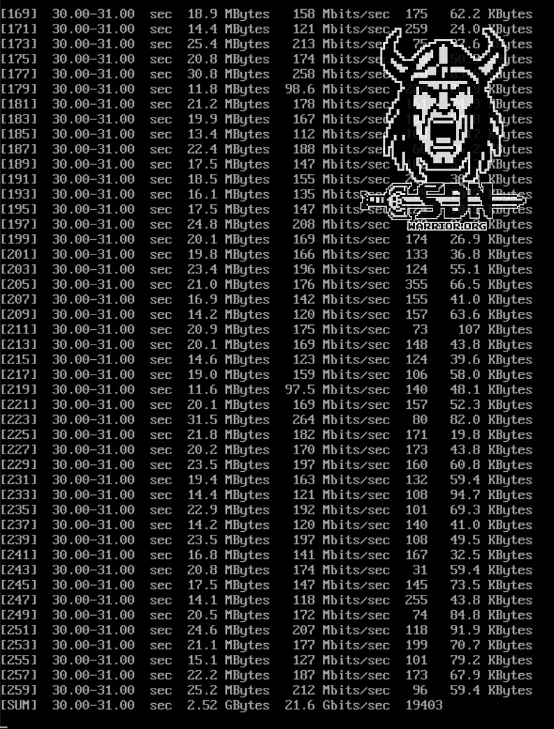
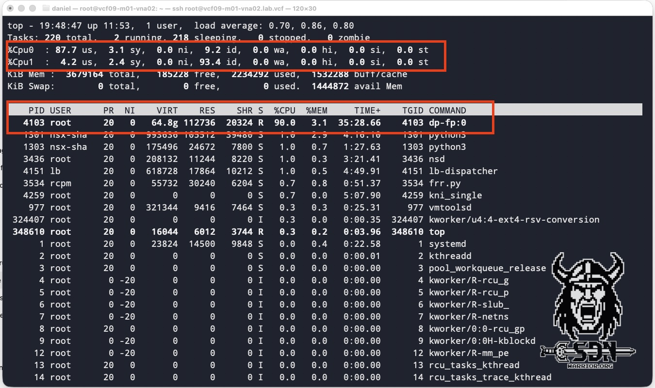
The tests were conducted using 128 parallel TCP streams in iPerf3 with a packet size of 1500 byte MTU. Each test VM was equipped with 4 vCPUs and 4 GB of RAM. As you can see in the screenshots, I achieved an impressive throughput of around 21.5 Gb/s with a VNA CPU core utilization of 90%. A small-form-factor VNA can use only one of its two vCPUs for the data path; the other CPU is responsible for the VNA itself. For my test results, it made no difference whether the test was unidirectional or bidirectional. You can also see in TOP that fastpath interface 0 was used. I think the results speak for themselves. Of course, you could get even more out of it with jumbo frames; conversely, with smaller packet sizes, packets per second become the dominant factor, and the datapath CPU is consumed by per-packet processing long before raw bandwidth becomes the bottleneck.
In my lab, I also did not observe any notable performance improvements from the larger form factor or the additional vCPUs. However, this result is mainly due to the limitations of my consumer-grade hardware, and should not be taken as an indication of the appliance’s general performance. In real-world environments, larger VNA appliances are expected to deliver better results, particularly when the underlying hardware can drive enough traffic to utilise all the available datapath CPUs. Based on my observations, I estimate that a Large VNA appliance with all four datapath vCPUs running at full capacity could achieve throughput comparable to that described in the enhanced datapath white paper for the extra large Edge. With the resources available in my lab, I was unable to generate sufficient load to push a Large VNA appliance anywhere near its CPU limits.
VPC Network Span
Another exciting feature introduced in version 9.1 is the vpc network span. This allows administrators to restrict the availability of a Transit Gateway to a specific set of vSphere clusters. This means that VPC subnets connected to the TGW are only available across the vSphere clusters within the span, rather than across all vSphere clusters within the environment. The feature itself is relatively simple and quick to explain. Spans can contain overlapping clusters; that is to say, a cluster can belong to multiple spans. There are two special types of span:
- Default span: By default, all vCenter clusters in the environment belong to a default span.
- Exclusive span: This is useful when you want to dedicate a set of vCenter clusters to a specific workload and prevent them from being shared across the environment. This prevents clusters from overlapping between spans and removes them from the default span. (Exclusive span is not supported if the span includes a VPC that uses VLAN-backed networks)
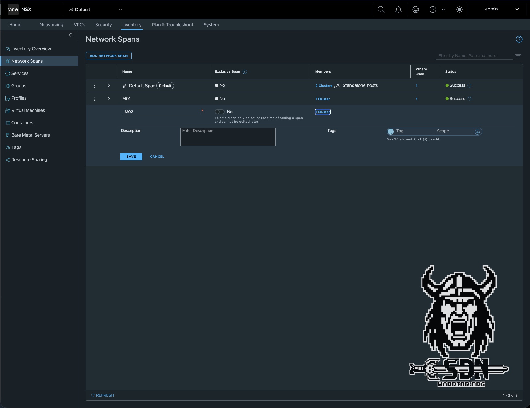
There are several ways to do this. The simplest is to create a new span via NSX in Inventory -> Network Spans -> Add Network Span. Here, you select the cluster, save it, and that’s it.
The solution here is to configure the span via the Desired State using the vCenter Client.
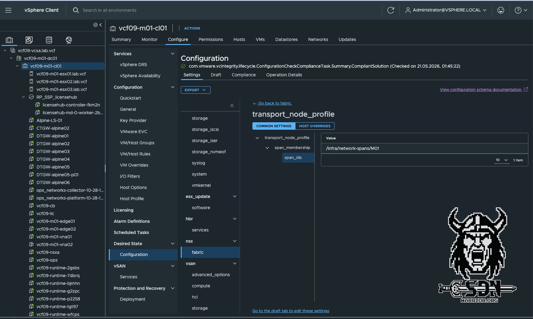
To use Spans, simply create a new transit gateway and assign it to an existing Span. Alternatively, you can edit an existing one. However, if, for example, there are already VPCs active in a vSphere cluster that are not within the Span you want to assign, the operation will fail.
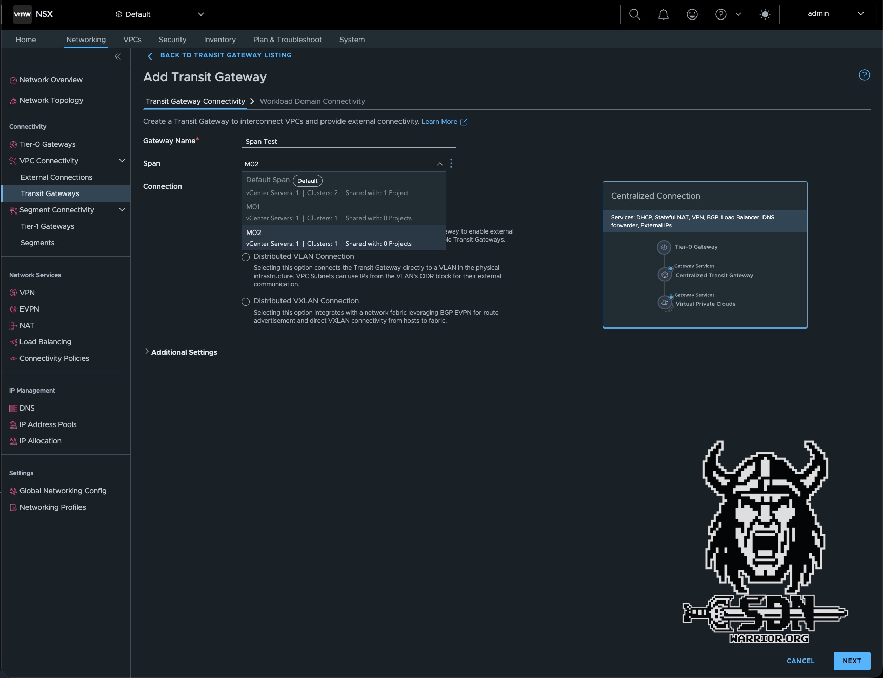
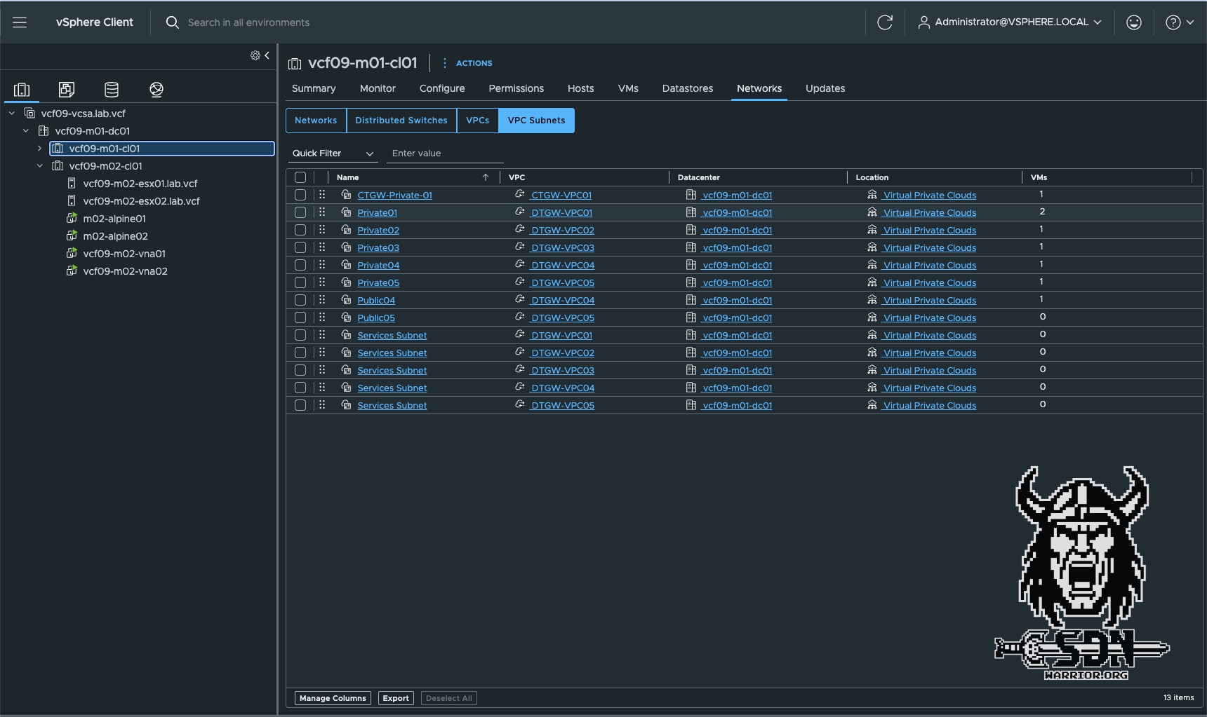
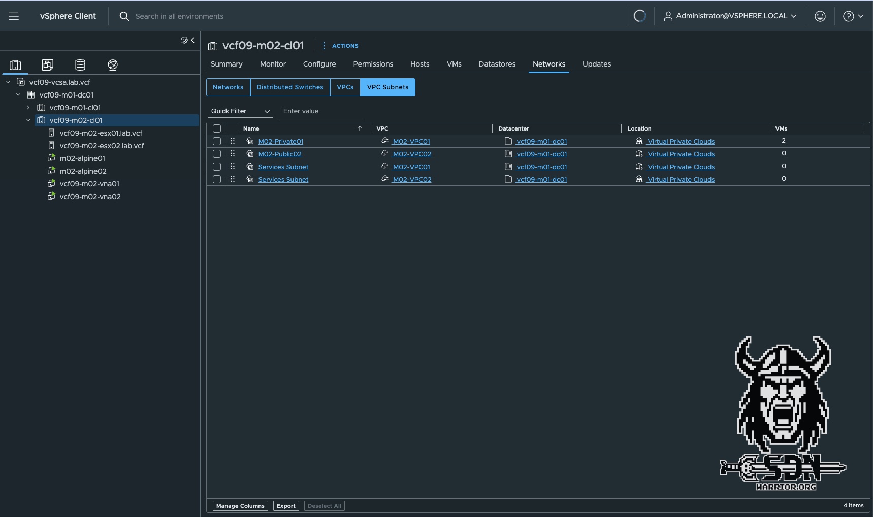
As you can see in the screenshots, only the VPCs in the M02 span are visible on the M02 cluster, and only the VPCs assigned to the M01 span are visible on the M01 cluster.
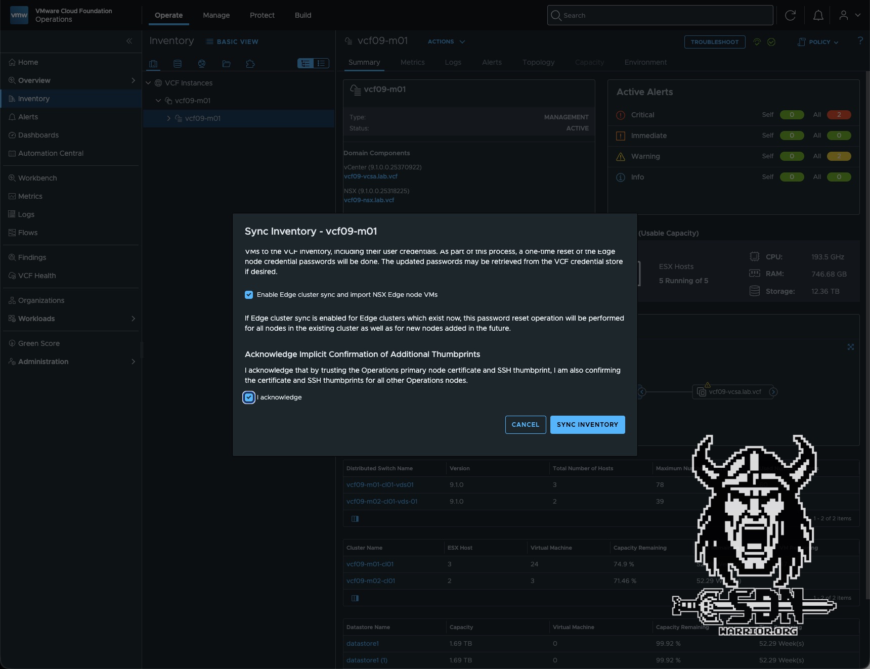
Password Management
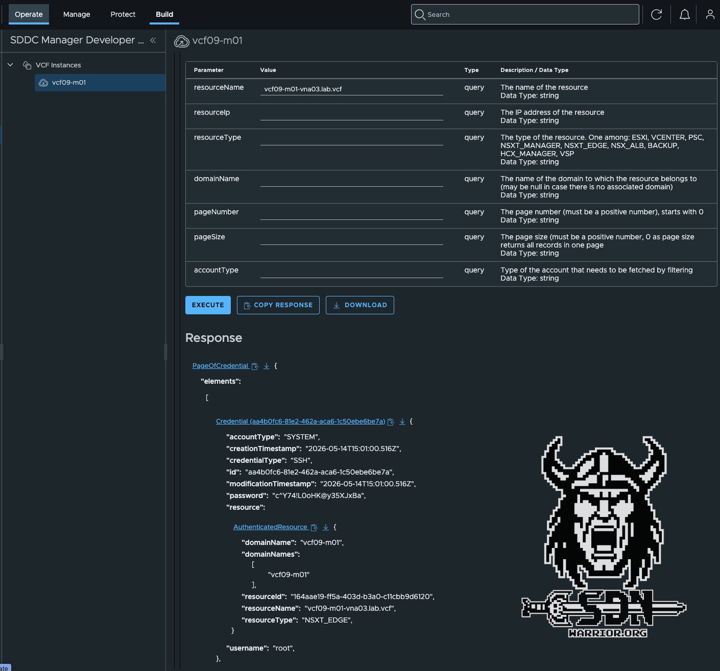
Centralized password management via VCF Operations is the only supported option. Local login credentials cannot be configured during VNA deployment. In VCF Operations, you can override the password as needed, but this requires that you have the account password that was randomly generated during installation. However, this isn’t a major issue; the initial passwords can be retrieved via the SDDC API. You can do this in Operations under Build -> Developer Center -> APIs & SDKs -> SDDC Manager API or using any API client. Since I’m lazy, though, I prefer to do it via Operations. It’s important to use the API call (GET /v1/credentials). The easiest way to find the correct credentials is to specify resourceName as a parameter; this is the FQDN of the VNA appliance. With the initial password, you can easily set your desired password via VCF Operations and Password Management.
In the future, password management will be removed from SDDC Manager and will be managed exclusively through VCF Operations. The current solution is therefore more of a temporary measure. This is also evident from the fact that the VNA is still listed as an “Edge” in the SDDC Manager UI.
Central-node config
If you’ve made it this far—congratulations. I’d like to wrap up this article with a simple topic. You may have wondered how the VNA manages to deploy with so little information. There’s a simple reason for this: the central node configuration. The VNA retrieves important information, such as DNS or NTP, from the central node configuration profile. This can be customized and configured under System -> Fabric -> Profiles -> Node Profiles.
Conclusion
My conclusion remains pretty much the same as in my first article. VNA is an exciting alternative or complement to the traditional edge cluster. It stands out for its simple configuration and the ease with which you can scale in and out. If I had to nitpick, I’d like to see a better password management workflow. It would be easy to make the automatic generation of passwords optional. Otherwise, I’ll just mention that the topic of VPCs and VNA isn’t exhausted yet, as there are still a few topics that didn’t make the cut. So I think there will be a third part coming soon.
