VCF 9.1 - DTGW & VNA: the route controller within me
In this article, I’ll take another look at VPCs and the VNA. This time, the VNA acts as the route controller, and the VPC is connected via VXLAN/EVPN using Type 5 routes.
5852 Words // ReadTime 26 Minutes, 36 Seconds
2026-07-11 13:00 +0200
Introduction
Oh no, not another one of those blogs—don’t you ever get tired of VPCs? To be honest, no, because VCF 9.1 offers a ton of new possibilities in this area, and I’m sure we’re still a long way from discovering its full potential. This article will focus on how to apply the Distributed VXLAN Connectivity Model in practice and in the lab. I hope you’ve brought enough coffee, because I’m afraid this might turn into another long journey down the rabbit hole.
But what exactly can I do with it?
Well, the big advantage is that I don’t need a stretched Layer 2 network in my data center, as is the case with the Distributed VLAN Connectivity Model (read here or here); I can use my BGP EVPN control plane, dynamic Type-5 prefix advertisements, and direct VXLAN connectivity between ESX TEPs and an external Border Gateway (BGW).
Unlike the Distributed VLAN Connectivity Model, the Distributed VXLAN Connectivity Model supports the multi-rack Layer 3 vSphere cluster model for workloads, thereby enabling Layer 3 separation of the racks—meaning the Layer 2 fault domain remains within the rack and is clearly delineated. To be fair, however, it must be noted that due to the active/standby configuration, a Layer 2 network is required for the BGP-EVPN interface; however, only routing information is exchanged over it, and no workload traffic flows through it.
Of course, it must be said that where there is light, there is also shadow—namely, that my physical network is admittedly somewhat more complex than it needs to be for a distributed transit gateway with a Layer 2 connection. However, this isn’t something NSX can be blamed for; it’s simply part of the deal when you want to use VXLAN/EVPN in general. The actual setup in NSX is very simple.
I won’t be covering the basics of VPC in this post. You can read about the VPC Basics here, here, or here.
VXLAN Basics
We’ll need a little theory here. However, I’ll only touch on these topics briefly, since my main goal in this article is to demonstrate the actual implementation. VXLAN stands for Virtual Extensible LAN. The basic concept is relatively simple: you take an existing IP network—known as the underlay—and build a logical network on top of it, known as the overlay. This will sound familiar to any NSX administrator—after all, NSX does more or less the same thing. But the differences are subtle. In short, VXLAN enables a Layer 2 network over a Layer 3 network. Each VXLAN segment has an identifier called VNI, which is 24-bit and allows to extend the VXLAN values to around 16 Million segments of VXLAN to work on.
VXLAN vs Geneve
Even though the two protocols are very similar, Geneve has a few advantages over VXLAN. For one thing, all fields in VXLAN have a fixed size; for another, VXLAN does not have a protocol identifier and therefore always assumes an Ethernet payload.
| Parameter | VXLAN | GENEVE |
|---|---|---|
| Developed by | VMware, Arista Networks, and Cisco | VMware, Microsoft, Red Hat, and Intel |
| Protocol | UDP | UDP |
| Port number | 4789 | 6081 |
| Header length | 8 bytes | 16 bytes |
| Transport security, service chaining, in-band telemetry | Not supported | Supported |
| RFC | VXLAN is documented by the IETF in RFC 7348 | RFC 8926 |
| Protocol identifier | No | Yes |
| Non-client payload indication | No | Yes |
| Extensibility | No. All fields in the VXLAN header have predefined values. | Yes |
| Term used for tunnel endpoints | VTEP | TEP |
EVPN VXLAN vs Static VXLAN
Depending on the provider, there are various implementations of VXLAN. The simplest of these is probably static VXLAN. With a static VXLAN configuration, most of the information must be configured manually. Each VTEP must be added to the appropriate segment. When a new VTEP interface is added, the configuration must be manually updated on all other devices. This is still feasible in small labs or simple environments, but becomes increasingly complex and error-prone as the network grows. “BUM” traffic is always flooded to all VTEP interfaces in static environments and can lead to problems as the network grows.
EVPN VXLAN solves this problem by adding a control plane. VXLAN continues to handle the actual data transport. MP-BGP EVPN is used for the dynamic exchange of information about MAC and IP addresses, as well as VNIs and routes. Instead of using a static mapping, network devices learn this information from each other via MP-BGP. EVPN is also a standard that is generally supported by all major providers, including NSX.
Type 2 vs Type 5
A Type 2 route informs the EVPN fabric of the VTEP interface associated with a specific MAC address and, in many cases, the corresponding IP address as well (depending on the vendor and implementation; the IP address is optional for Type 2). For example, if a virtual machine has the MAC address 00:50:56:a8:ab:d8 and the IP address 192.168.10.20, the control plane informs the fabric of the VTEP interface on which it can be found. Type 2 routes are used to extend the Layer 2 network across multiple switches and VTEP endpoints.
A Type 5 route, on the other hand, is used to advertise IP prefixes. It does not specify a single MAC address or a single IP address (although individual IP addresses can also be advertised as a /32 prefix). Using this routing information, the EVPN fabric can route traffic specifically to the correct VTEP interface for subnets. A Type 5 route looks similar to a normal route; it provides a next hop for a subnet. Other devices in the fabric do not know the MAC addresses within the subnet; they only need to know that the network exists and where the routed traffic must be sent. Type 5 routes cannot be used to stretch a Layer 2 network; they only ensure Layer 3 reachability and do not provide Layer 2 connectivity.
Distributed VXLAN Connectivity Model
With VCF 9.1, another EVPN implementation was added to NSX. The old EVPN implementation (EVPN inline mode wth NSX Edges) has not been changed and remains in place. However, it cannot be used for VPCs. A new feature is the ability to use VXLAN for VPCs via the Route Controller. The Distributed VXLAN Connectivity Model was born. This feature integrates NSX with the physical EVPN-VXLAN fabric. The cool thing about this is that GENEVE is still used for east-west traffic between ESX hosts, but VXLAN is used for north-south traffic to the physical EVPN-VXLAN fabric. In this case, the ESX TEP interface can handle both GENEVE and VXLAN simultaneously. As mentioned at the beginning of this article: Unlike an implementation that uses the distributed VLAN connectivity model, this means you do not have to extend an external VLAN across the physical fabric.
Basic functionality of the route controller
Here, I’ll just give a rough overview of how route exchange works. In this setup, the route controller is never part of the data path. The active route controller advertises a /32 IPv4 host route for each VM in the VPC’s public network or External IP (stateless NAT). The VTEP interface of the ESX server on which the VM is running is specified as the next hop in the Type 5 route. The EVPN route controller collects this information about each workload VM via the standard CCP (Central Control Plane) channel from the individual ESX hosts through the NSX Manager. The EVPN gateway(s) in the physical EVPN-VXLAN fabric forward prefixes from physical endpoints, networks, or a default route to the EVPN route controller, including the next-hop information configured on each EVPN gateway. To keep the forwarding table as small as possible on each ESX host where a Distributed Transit Gateway is instantiated, the EVPN route controller sends only the default route and the next hop of the EVPN gateway to each ESX host via the NSX Manager. The physical fabric learns all host routes from the route controller and adds them to its routing table for the corresponding VRF. This ensures IP connectivity on both sides.
Lab Setup
To keep the lab as simple as possible, I decided to use a virtual VyOS router as the border gateway router. The Vyos router runs on a standalone ESX server outside my VCF environment; since having something like this nested within my VCF environment consistently leads to problems, I always perform such tests on dedicated hardware. I’m using a Route Controller in an active/standby configuration. The following diagram clearly illustrates the setup. I have two test Linux VMs: Alpine02 is part of my VPC’s public network (10.100.0.8/29), and Alpine01 is in the VRF tenant network 192.168.100.0/24.
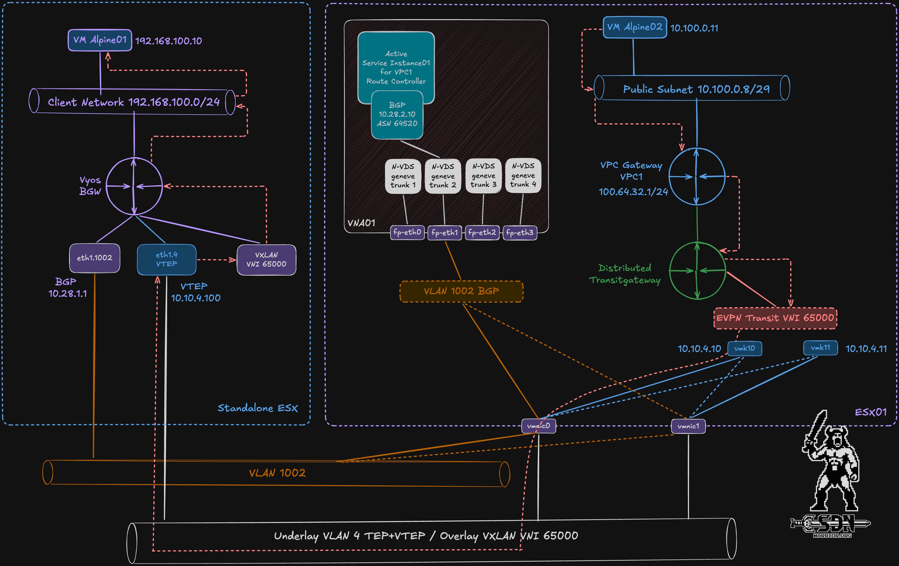
In hindsight, it wasn’t the smartest idea to name my VRF tenant, but to be honest, I’m too lazy to adjust the configuration and graphics at this point. Both the Vyos router’s VTEP interface and the ESX TEP interfaces are in VLAN 4 and on the same IP network. In a real-world setup, these would be in different VLANs, but I didn’t want to introduce another routing instance into the underlay network. The actual BGP session is initialized over VLAN 1002. Both VLANs 1002 and 4 belong to the Vyos default VRF. The VXLAN VNI used is 65000.
In a real-world scenario, the setup is, of course, somewhat different. Normally, for EVPN peering between the route controller and the EVPN gateway, a loopback interface in the global routing context on the physical fabric is used. In addition, the route controller BGP interfaces are often in a customer-specific VRF. The same can and should apply to the TEP interfaces of the ESX servers, which necessitates route leaking, since IP connectivity is required between BGP peers and between TEP and VTEP interfaces. In my lab setup, both the BGP peers and the VTEP and TEP interfaces are in the global routing context, which significantly simplifies the setup and makes route leaking obsolete. Of course, my lab setup is not a good design for real-world environments.
External Connection Settings
| Component | Value | Description |
|---|---|---|
| VyOS BGP AS | 64515 |
BGP autonomous system used by VyOS |
| NSX Remote AS | 64520 |
BGP autonomous system used by the NSX Route Controller |
| VyOS BGP Peer IP | 10.28.2.1 |
VyOS IP used for BGP peering with the NSX Route Controller |
| NSX Route Controller Peer | 10.28.2.10 |
EVPN/BGP VIP peer on the NSX side |
| Route Controller Peer IP | 10.28.2.100 |
Route Controller 1 Appliance IP |
| Route Controller Peer IP | 10.28.2.101 |
Route Controller 2 Appliance IP |
| VyOS VTEP IP | 10.10.4.100 |
VyOS VXLAN source address |
| ESX TEP IP | 10.10.4.10 |
ESX01 VXLAN source address |
| ESX TEP IP | 10.10.4.11 |
ESX01 VXLAN source address |
| Global BGP Router ID | 10.28.2.1 |
Router ID used in the global VyOS BGP instance |
| Tenant VRF Router ID | 10.10.4.100 |
Router ID used inside the VyOS tenant VRF BGP instance |
| EVPN L3 VNI | 65000 |
Layer 3 VNI used for the tenant VRF / external connection |
| VyOS EVPN RD | 10.10.4.100:10 |
Route Distinguisher used by VyOS for tenant EVPN routes |
| NSX EVPN RD | 10.28.2.10:65000 |
Route Distinguisher used by NSX for the External Connection |
| EVPN RT Import | 65000:10 |
Route Target imported by both sides |
| EVPN RT Export | 65000:10 |
Route Target exported by both sides |
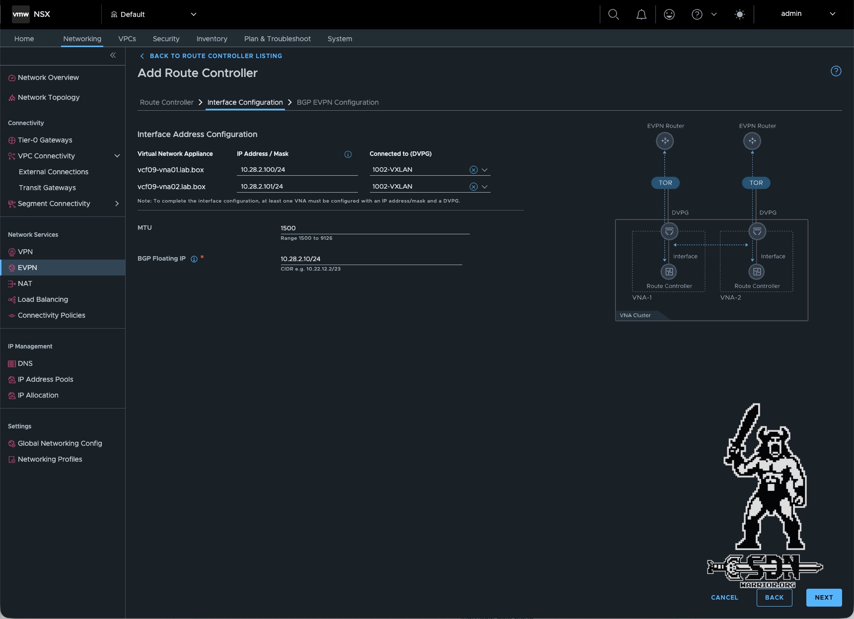
The attentive reader will have noticed that the Route Controller has three IP addresses for the BGP session. This is due to the active-standby configuration. The BGP peering is established on a VIP of the Route Controller cluster, and each Route Controller also has an IP address in the BGP VLAN.
VyOS VRF Configuration
| VRF Name | Routing Table | VNI | Role |
|---|---|---|---|
default / global |
main |
N/A | Underlay connectivity, management, and BGP peering to the NSX Route Controller |
tenant |
100 |
65000 |
Tenant VRF used for EVPN VXLAN Layer 3 connectivity |
VyOS Physical and VLAN Interfaces
| Interface | Type | VLAN ID | IP Address | VRF | Description |
|---|---|---|---|---|---|
| eth0 | Physical | N/A | 192.168.10.40/24 |
Global | Management interface |
| eth1 | Physical | N/A | None | Global | Trunk interface toward NSX / fabric |
| eth1.4 | VLAN | 4 | 10.10.4.100/24 |
Global | Data plane interface, used as VXLAN VTEP source address |
| eth1.1002 | VLAN | 1002 | 10.28.2.1/24 |
Global | NSX Route Controller BGP peering interface |
| eth2 | Physical | N/A | 192.168.100.1/24 |
tenant | Untagged local client network inside the tenant VRF |
My VyOS uses 3 interfaces, though eth0 serves only as a management interface for me. However, this is simply due to the setup of my physical lab and may be optional for you. eth1 is a trunk interface through which BGP and VXLAN traffic flows. eth2 provides an untagged network for my Alpine01, allowing me to connect VMs to the client network and perform true end-to-end tests between VMs. eth2 is connected in my vCenter to a port group that also hosts my Alpine01 test VM.
VyOS Bridge Settings
| Bridge | MAC Address | Member Interface | VRF | Description |
|---|---|---|---|---|
br65000 |
00:53:00:65:00:00 |
vxlan65000 |
tenant |
L3VNI anchor bridge for the tenant VRF |
The bridge serves as an L3VNI anchor and does not have an IP address configured. I manually configured a MAC address, but normally VyOS should configure one automatically. It is important that the bridge is assigned to the tenant VRF; through the member interface, my L3VNI thus becomes part of the tenant VRF. Without this configuration, my VXLAN interface is not assigned to the correct VRF.
VyOS VRF Tenant Network
| Network | Interface | VRF | Purpose |
|---|---|---|---|
192.168.100.0/24 |
eth2 |
tenant |
Local client network connected to the VyOS tenant VRF |
192.168.100.1/24 |
eth2 |
tenant |
VyOS gateway IP for the local tenant network |
Route Distinguisher and Route Target Mapping
| Component | RD | Import RT | Export RT | Description |
|---|---|---|---|---|
| VyOS Tenant VRF | 10.10.4.100:10 |
65000:10 |
65000:10 |
RD and RT configuration on the VyOS side |
| NSX External Connection | 10.28.2.10:65000 |
65000:10 |
65000:10 |
RD and RT configuration on the NSX side |
Full VyOS Configuration
set interfaces bridge br65000 description 'L3VNI anchor for tenant VRF'
set interfaces bridge br65000 mac '00:53:00:65:00:00'
set interfaces bridge br65000 member interface vxlan65000
set interfaces bridge br65000 vrf 'tenant'
set interfaces ethernet eth0 address '192.168.10.40/24'
set interfaces ethernet eth1 description 'Trunk to NSX / Fabric'
set interfaces ethernet eth1 mtu '1700'
set interfaces ethernet eth1 vif 4 address '10.10.4.100/24'
set interfaces ethernet eth1 vif 4 description 'Data Plane - VXLAN VTEP in NSX TEP VLAN'
set interfaces ethernet eth1 vif 4 mtu '1700'
set interfaces ethernet eth1 vif 1002 address '10.28.2.1/24'
set interfaces ethernet eth1 vif 1002 description 'NSX Route Controller Peering / VXLAN Source'
set interfaces ethernet eth1 vif 1002 mtu '1700'
set interfaces ethernet eth2 address '192.168.100.1/24'
set interfaces ethernet eth2 description 'Untagged local client network in tenant VRF'
set interfaces ethernet eth2 vrf 'tenant'
set interfaces vxlan vxlan65000 description 'EVPN L3VNI 65000 toward NSX TGW'
set interfaces vxlan vxlan65000 mtu '1500'
set interfaces vxlan vxlan65000 port '4789'
set interfaces vxlan vxlan65000 source-address '10.10.4.100'
set interfaces vxlan vxlan65000 vni '65000'

set protocols bgp address-family ipv4-unicast import
set protocols bgp address-family ipv4-unicast redistribute connected
set protocols bgp address-family ipv4-unicast redistribute static
set protocols bgp address-family l2vpn-evpn advertise ipv4 unicast
set protocols bgp address-family l2vpn-evpn advertise-all-vni
set protocols bgp address-family l2vpn-evpn advertise-default-gw
set protocols bgp address-family l2vpn-evpn default-originate ipv4
set protocols bgp neighbor 10.28.2.10 address-family ipv4-unicast default-originate
set protocols bgp neighbor 10.28.2.10 address-family l2vpn-evpn soft-reconfiguration inbound
set protocols bgp neighbor 10.28.2.10 bfd
set protocols bgp neighbor 10.28.2.10 description 'NSX Route Controller RC-01'
set protocols bgp neighbor 10.28.2.10 remote-as '64520'
set protocols bgp neighbor 10.28.2.10 timers holdtime '3'
set protocols bgp neighbor 10.28.2.10 timers keepalive '1'
set protocols bgp neighbor 10.28.2.10 update-source '10.28.2.1'
set protocols bgp parameters bestpath as-path multipath-relax
set protocols bgp parameters graceful-restart stalepath-time '180'
set protocols bgp parameters no-hard-administrative-reset
set protocols bgp parameters router-id '10.28.2.1'
set protocols bgp system-as '64515'

set vrf name tenant protocols bgp address-family ipv4-unicast import
set vrf name tenant protocols bgp address-family ipv4-unicast redistribute connected
set vrf name tenant protocols bgp address-family ipv4-unicast redistribute static
set vrf name tenant protocols bgp address-family l2vpn-evpn advertise ipv4 unicast
set vrf name tenant protocols bgp address-family l2vpn-evpn advertise-default-gw
set vrf name tenant protocols bgp address-family l2vpn-evpn rd '10.10.4.100:10'
set vrf name tenant protocols bgp address-family l2vpn-evpn route-target export '65000:10'
set vrf name tenant protocols bgp address-family l2vpn-evpn route-target import '65000:10'
set vrf name tenant protocols bgp address-family l2vpn-evpn vni 65000
set vrf name tenant protocols bgp parameters graceful-restart stalepath-time '180'
set vrf name tenant protocols bgp parameters no-hard-administrative-reset
set vrf name tenant protocols bgp parameters router-id '10.10.4.100'
set vrf name tenant protocols bgp system-as '64515'
set vrf name tenant table '100'
set vrf name tenant vni '65000'
Creating the Route Controller Cluster
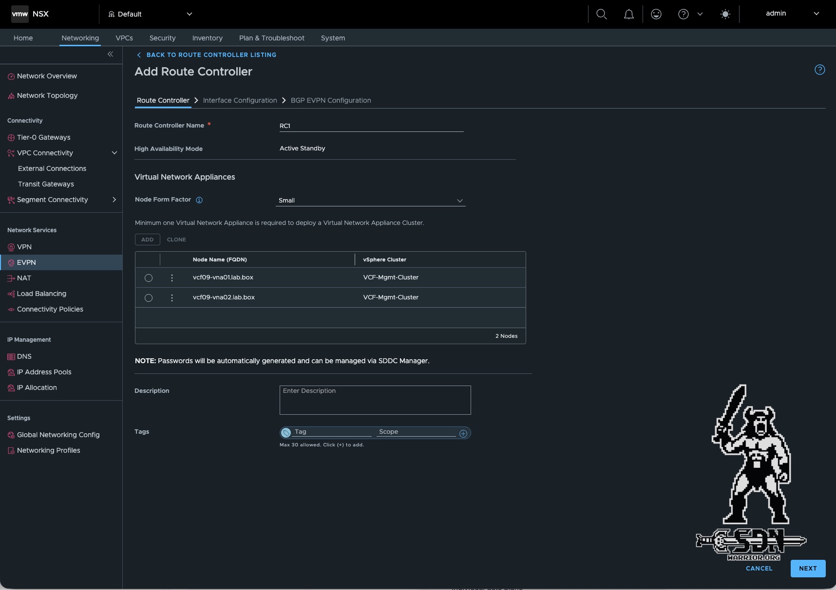
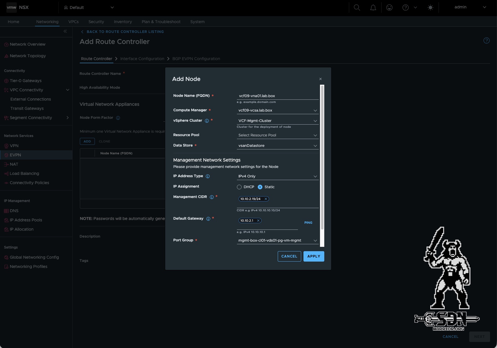
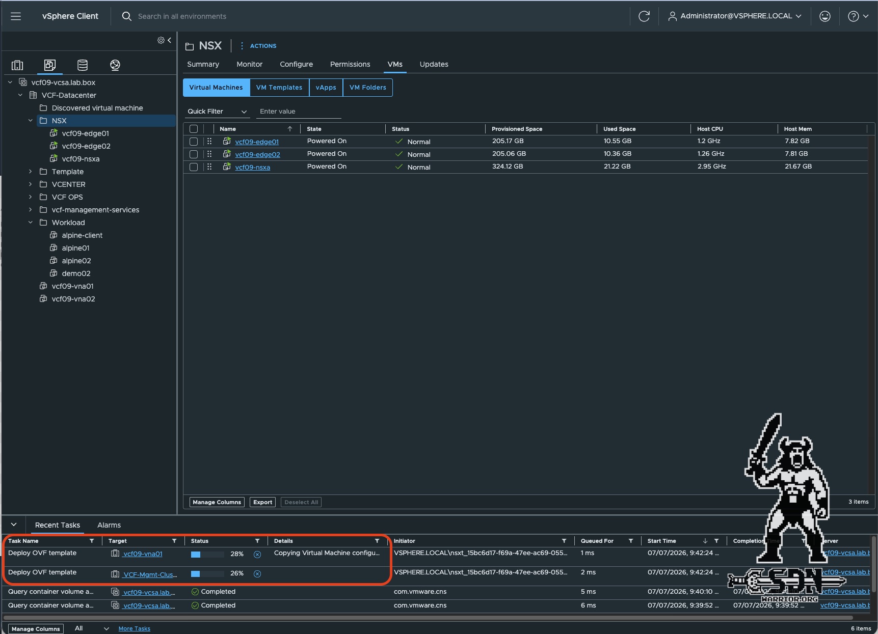
First, the Route Controller is deployed. This is not done from vCenter or in NSX via the VNA deployment, but rather in NSX under Networking -> EVPN -> Route Controller -> ADD ROUTE CONTROLLER. The process is largely the same as for a standard VNA deployment. In my lab, I use the “Small” form factor. “Medium” is recommended for production environments. A larger form factor is not currently available, nor is it needed. A medium-size route controller already has enterprise-grade scale and can manage more than 100,000 prefixes. Since the route controller is only part of the control plane, this form factor is sufficient. As shown in the screenshots, the parameters that must be specified are identical to those for a VNA deployment. You’ll need an FQDN, a management IP address, a vSphere cluster, a datastore, and a port group. The route controller can be deployed as a single node or a 2-node cluster. In my setup, I’m using a 2-node cluster.
Things get more interesting in the next step, where you need to configure the route controller interfaces. Here, you must select the correct port group—in my case, it’s VLAN 1002. The port group must be created before deployment and is used for BGP peering. Each route controller appliance is assigned a local IP address in this network, and a floating IP is also configured for BGP peering. In addition, my VyOS router on the same network also has a BGP peering IP (see the table earlier in the article).
Next, the BGP peering must be configured. ECMP and Multipath Relax don’t make much sense in my lab setup, since I currently have only one border gateway router. Additionally, a local AS for NSX and one for VyOS must be configured. A second BGP peer is optional. Another important parameter is the BGP max hop limit, which is set to 1 by default and can be increased to up to 256 hops. Since all the BGP peers in my lab are on the same VLAN, I obviously don’t have any routing hops in between, but in real-world environments, the situation is different, since MP-BGP EVPN is generally never directly peered (keyword: loopback interface) but are always multi-hop. It’s also important to note that a max hop of 1 means the BGP peering partners have no routing hops in between them and are on the same network! For the peering to work, the correct hop limit must be configured on both sides. BFD should be disabled. Furthermore, BGP timers cannot be adjusted here; they must be modified afterward.
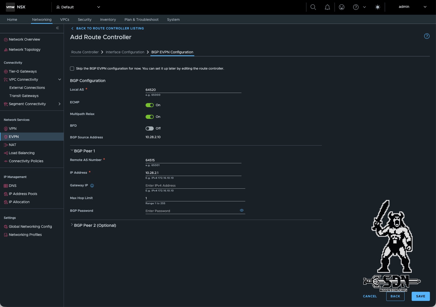
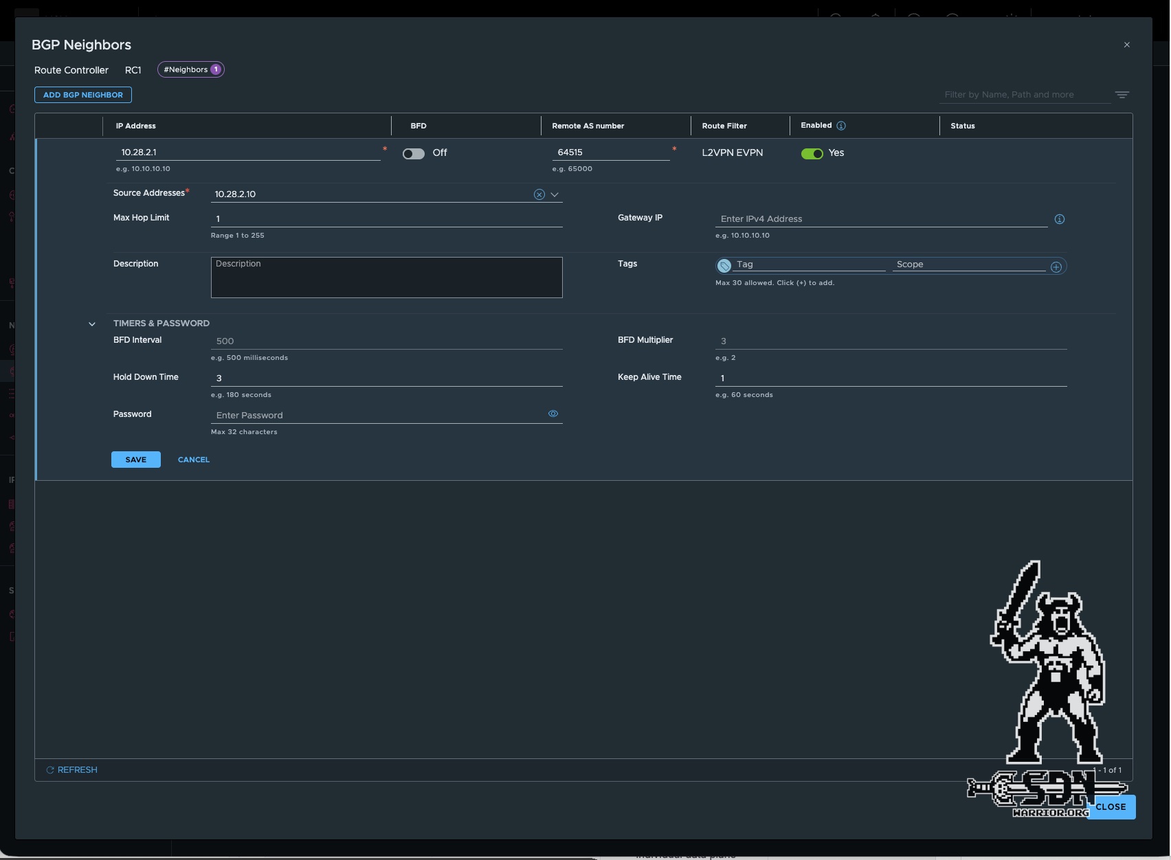
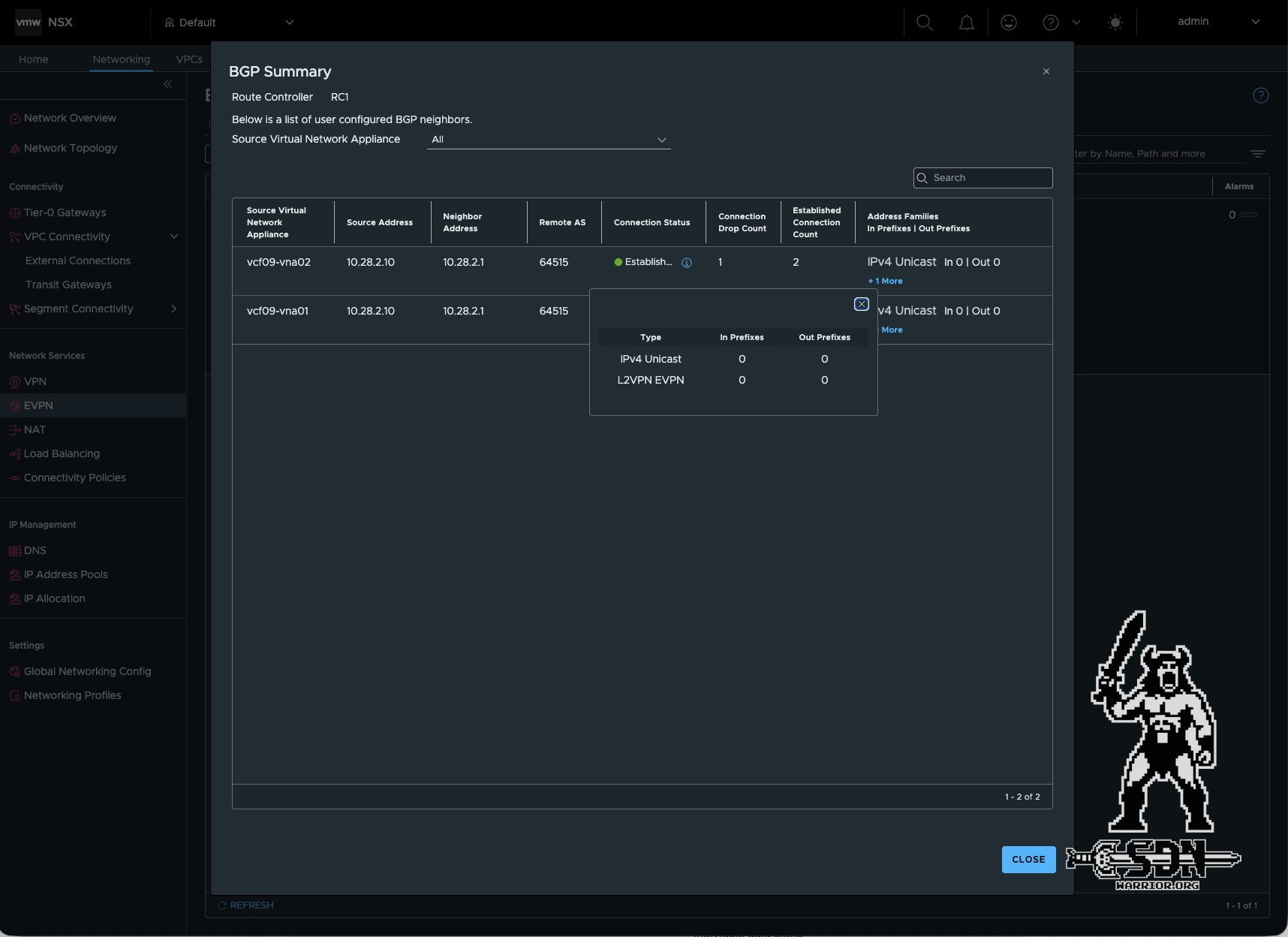
Once this step has also been configured, the route controller appliances are automatically deployed. It only took me about 10 minutes to get it done. After that, all I have to do is adjust the BGP timers. To do this, click “Edit” under Networking -> EVPN -> Route Controller for the deployed route controller cluster. You can adjust the timers in the Neighbor settings. Broadcom recommends setting the timers to a 1-second keepalive time and a 3-second hold-down time. These settings are relatively aggressive, and depending on your infrastructure, different values may be more appropriate. You can check the current BGP session by clicking “Generate BGP Summary” on the route controller cluster. If everything is correct, one route controller should show “Established” and the other “Idle” (active/standby setup).
Setup the Transit Gateway
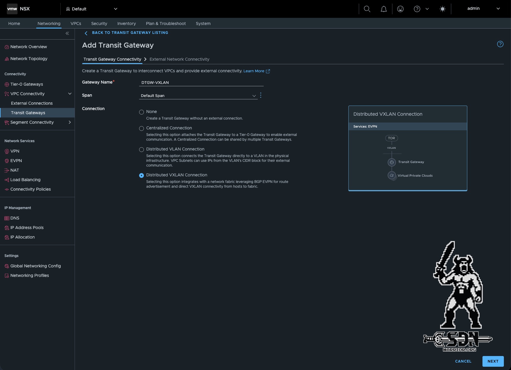
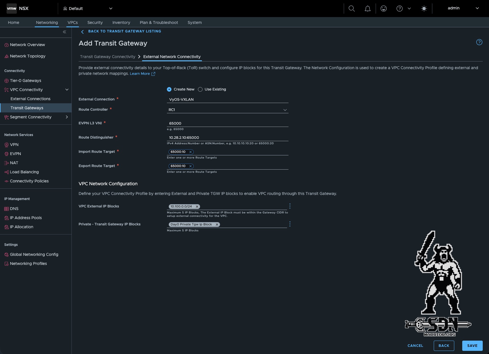
Next, you need to create the transit gateway. As before, you can do this in NSX under Networking -> Transit Gateway -> ADD TRANSIT GATEWAY. Here, you must select “Distributed VXLAN Connection.” Under “External Network Connectivity,” you must specify the EVPN L3 VNI. In my setup, this is 65000. Each External Connection can have at most one Layer 3 VNI. The Route Distinguisher is used to uniquely identify routes, since in EVPN setups, multiple tenants or VRFs can use the same IP range.
The next two important settings are the import and export route targets. The route target is a BGP extended community used to determine which EVPN routes are imported into or exported from which VRF. I decided to use the VNI as the namespace for the naming scheme, and I chose 10 as my local value for the VRF/external connection. Therefore, in my setup, 65000:10 would be my route target. Since I’m only establishing a simple bidirectional connection between the VyOS VRF and the NSX transit gateway, it’s fine to use the same import/export route target in both NSX and VyOS. This simplifies the setup.
The remaining settings are the same as for a standard transit gateway; you’ll need an external IP block and a private transit gateway IP block.
Creating the VPC
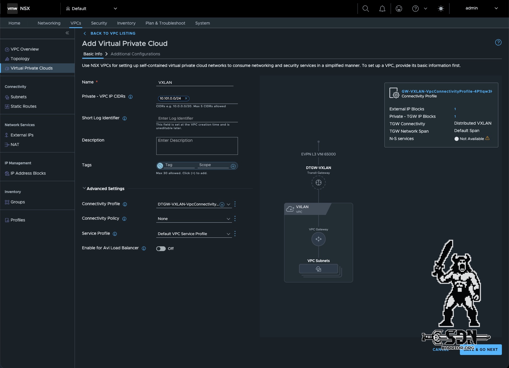
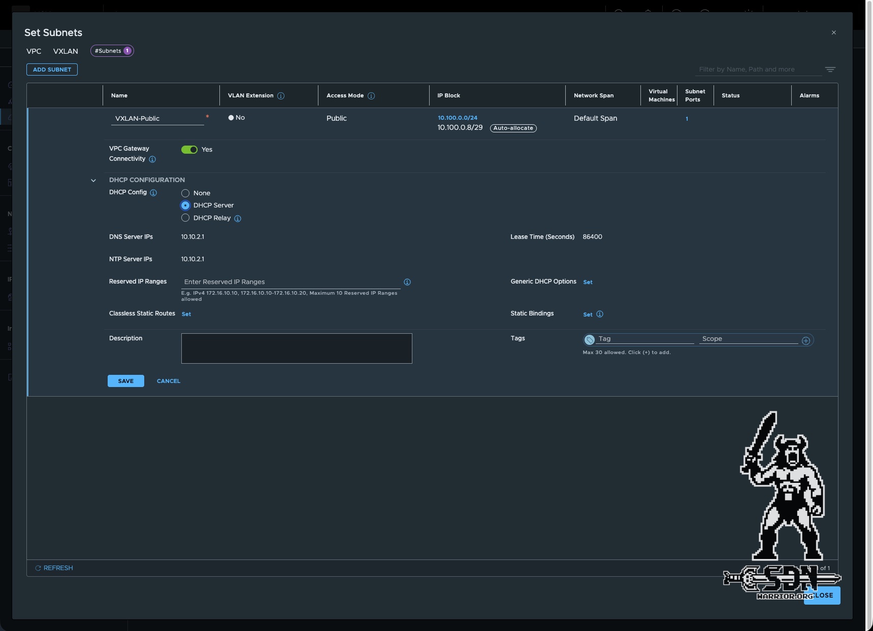
The final step is to create the actual VPC; this is no different from setting up other VPCs. The only important thing here is to select the correct connectivity profile; otherwise, the VPC will be created on my centralized transit gateway in my lab, and that’s not what we want. I use a DHCP server in my public subnet because I’m lazy. Once a VM has been created and connected to the public segment, I can start the first tests.
Test the Setup
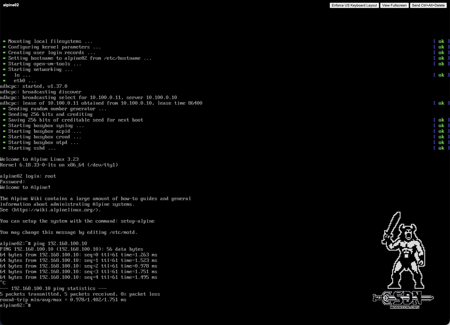
By far the easiest test is a simple ping test from Alpine02 (10.100.0.11) to Alpine01 (192.168.100.10) or vice versa. As expected, the result is successful.
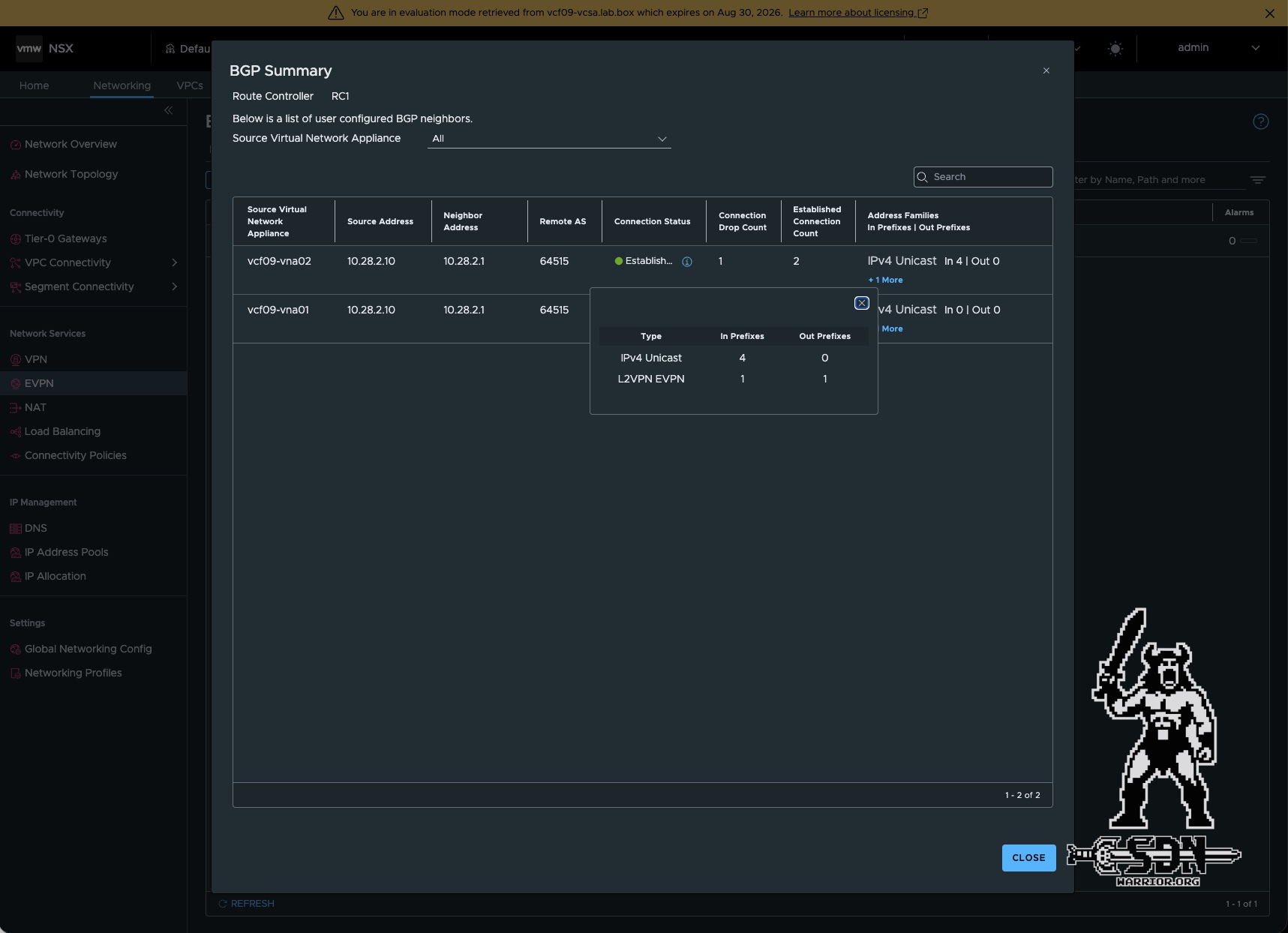
In addition, I check the BGP summary in NSX, and now see an “In Prefix” and an “Out Prefix” displayed for L2VPN EVPN.
Of course, I’ll also take a look at all of this via the CLI. To do that, you need to connect via SSH to the ESX host where the Alpine02 test VM is running, and then you can read the forwarding table of the transit gateway. You can use the esx cli command net-vdr -Il --brief to display the distributed router UUIDs; these can be identified based on the API path.
[root@vcf09-esx01:~] net-vdr -Il --brief

DR Instance Information :
---------------------------

State Legend: [A: Active], [D: Deleting], [X: Deleted], [I: Init]
State Legend: [SF-R: Soft Flush Route], [SF-L: Soft Flush LIF]
State Legend: [SF-I: Soft Flush Instance]

DR Id      #Lifs   #Routesv4 #Routesv6    State      DR UUID
-------    -----   --------- ---------    -----      ---------
0xc0d      2       3         5            A          5223a62b-7950-4109-a15a-cd890c165d75 (/orgs/default/projects/default/vpcs/VXLAN,DTGW-VXLAN)
0xc0a      2       3         4            A          bb4806e3-97da-481f-8fa2-7d736353d2bc (/orgs/default/projects/default/transit-gateways/DTGW-VXLAN)
For my verification, I am interested in the forwarding table of my distributed transit gateway (DTGW-VXLAN). You can view the forwarding table using the NSXCLI command get gateway <UUID> forwarding. Here you can see that the border gateway router is listed in the table as the default route via the VTEP IP address.
vcf09-esx01.lab.box> get gateway bb4806e3-97da-481f-8fa2-7d736353d2bc forwarding
Tue Jul 07 2026 UTC 23:06:24.130
                                       Logical Routers Forwarding Table
--------------------------------------------------------------------------------------------------------------
Flags Legend: [U: Up], [G: Gateway], [C: Connected], [I: Interface]
[H: Host], [R: Reject], [B: Blackhole], [F: Soft Flush], [E: ECMP]
[S1|S2|S3: TGW Private|Public|External Route Scope]

                   Network                               Gateway                Type               Interface UUID
==============================================================================================================
0.0.0.0/0                                              10.10.4.100              UGS3    375d0cb0-22ba-43d0-9a22-7bfbc987b4b3
10.100.0.8/29                                           100.64.0.1              UGS2    a26e3e84-2d70-55a1-8b10-af54511833e7
100.64.0.0/31                                            0.0.0.0                UCI     a26e3e84-2d70-55a1-8b10-af54511833e7
fcc8:2d54:d88a:8c00::/64                                    ::                  UCI     a26e3e84-2d70-55a1-8b10-af54511833e7
fe80:404:100:0:50:56ff:fe56:4452/128                        ::                  UCI     a26e3e84-2d70-55a1-8b10-af54511833e7
ff02:404:100::1:ff00:1/128                                  ::                  UCI     a26e3e84-2d70-55a1-8b10-af54511833e7
ff02:404:100::1:ff56:4452/128                               ::                  UCI     a26e3e84-2d70-55a1-8b10-af54511833e7
In VyOS, you can use the command show bgp l2vpn evpn route to view the routes and see which transit gateway or RD they originate from.
vyos@vyos:~$ show bgp l2vpn evpn route
BGP table version is 1, local router ID is 10.28.2.1
Status codes: s suppressed, d damped, h history, * valid, > best, i - internal
Origin codes: i - IGP, e - EGP, ? - incomplete
EVPN type-1 prefix: [1]:[EthTag]:[ESI]:[IPlen]:[VTEP-IP]:[Frag-id]
EVPN type-2 prefix: [2]:[EthTag]:[MAClen]:[MAC]:[IPlen]:[IP]
EVPN type-3 prefix: [3]:[EthTag]:[IPlen]:[OrigIP]
EVPN type-4 prefix: [4]:[ESI]:[IPlen]:[OrigIP]
EVPN type-5 prefix: [5]:[EthTag]:[IPlen]:[IP]

   Network          Next Hop            Metric LocPrf Weight Path
                    Extended Community
Route Distinguisher: 10.10.4.100:10
 *>  [5]:[0]:[24]:[192.168.100.0] RD 10.10.4.100:10
                    10.10.4.100              0         32768 ?
                    ET:8 RT:65000:10 Rmac:00:53:00:65:00:00
Route Distinguisher: 10.28.2.10:65000
 *>  [5]:[0]:[32]:[10.100.0.11] RD 10.28.2.10:65000
                    10.10.4.10               0             0 64520 i
                    RT:65000:10 ET:8 Rmac:00:50:56:6f:02:b4

Displayed 2 prefixes (2 paths)
As can be seen in the output, the EVPN routing table has two Type 5 prefix routes. The prefix 192.168.100.0/24 originates from the VyOS router itself and uses the route distinguisher 10.10.4.100:10 and the local VyOS VTEP interface (10.10.4.100) as the next hop. The weight parameter of 32768 indicates that the route was generated locally. The host route 10.100.0.11/32 is received from the Route Controller in AS 64520. It uses the Route Distinguisher 10.28.2.10:65000 and points to one of the ESX TEP Interfaces (10.10.4.10). Both routes use Route Target 65000:10, VXLAN encapsulation (ET:8), and include the router MAC required for Layer-3 forwarding through the corresponding L3VNI.
The routing table for the tenant VRF looks like this:
vyos@vyos:~$ show ip route vrf tenant
Codes: K - kernel route, C - connected, L - local, S - static,
       R - RIP, O - OSPF, I - IS-IS, B - BGP, E - EIGRP, N - NHRP,
       T - Table, v - VNC, V - VNC-Direct, A - Babel, F - PBR,
       f - OpenFabric, t - Table-Direct,
       > - selected route, * - FIB route, q - queued, r - rejected, b - backup
       t - trapped, o - offload failure

IPv4 unicast VRF tenant:
B>* 10.100.0.11/32 [20/0] via 10.10.4.10, br65000 onlink, weight 1, 01:15:12
C>* 192.168.100.0/24 is directly connected, eth2, weight 1, 04:37:27
L>* 192.168.100.1/32 is directly connected, eth2, weight 1, 04:37:27
If I now deploy another test VM in the public subnet, the VyOS router receives another /32 route for that VM.
vyos@vyos:~$ show ip route vrf tenant
Codes: K - kernel route, C - connected, L - local, S - static,
       R - RIP, O - OSPF, I - IS-IS, B - BGP, E - EIGRP, N - NHRP,
       T - Table, v - VNC, V - VNC-Direct, A - Babel, F - PBR,
       f - OpenFabric, t - Table-Direct,
       > - selected route, * - FIB route, q - queued, r - rejected, b - backup
       t - trapped, o - offload failure

IPv4 unicast VRF tenant:
B>* 10.100.0.11/32 [20/0] via 10.10.4.10, br65000 onlink, weight 1, 01:16:21
B>* 10.100.0.12/32 [20/0] via 10.10.4.11, br65000 onlink, weight 1, 00:00:08
C>* 192.168.100.0/24 is directly connected, eth2, weight 1, 04:38:36
L>* 192.168.100.1/32 is directly connected, eth2, weight 1, 04:38:36
As shown in the routing table, this VM has a different TEP IP address even though it is running on the same ESX server. By distributing traffic across the available TEP interfaces, NSX ensures load balancing and thereby increases physical throughput.
BFD and Other Pitfalls
My first instinct is usually to call BFD right away when BGP is involved, but with the Route Controller, that’s the wrong approach and can even be counterproductive. I’ll just quote Broadcom here:
If you don’t follow these instructions—as I did at first—you’ll also get false-positive errors in NSX, since only the active route controller can establish a BFD session. In addition, BFD and BGP packets may take different paths due to ECMP (if enabled), which could cause the BGP-EVPN session to be terminated. In such a case, the graceful restart mechanism would not take effect either. To ensure a fast failover, fast non-default BGP timers are absolutely essential. As I mentioned earlier, in my lab I use very fast timers: 1 second for hellp and 3 seconds for hold. It’s important to note that these can only be configured after deployment.
Configure “Graceful Restart” on the border gateway router; by default, the route controller has “Graceful Restart” enabled with a duration of 180 seconds. “Graceful Restart” allows BGP routes to be temporarily retained as obsolete routes under certain conditions, but does not guarantee that these routes will remain in the kernel’s forwarding table. In my lab, “Graceful Restart” was successfully negotiated between VyOS and the NSX Route Controller. However, the “Forwarding State” bit was not set for either IPv4 unicast or L2VPN-EVPN. As a result, VyOS was still able to remove the Type 5 EVPN route from the active tenant VRF’s routing table during the failover. Nevertheless, “Graceful Restart” offers advantages, as previously learned routes can be processed in a more controlled manner, and it uses End-of-RIB markers to signal when the re-advertisement of the routes is complete. With my settings, I experienced no measurable packet loss during a controlled failover (NSX maintenance mode); during an uncontrolled failover (powering off the active route controller), there was a single ping dropout. Since VyOS is not officially supported, I unfortunately cannot say how it would behave with a supported physical fabric. However, Broadcom recommends using and configuring “Graceful Restart.”
Another thing is that you can’t use auto SNAT because you don’t have a VNA for stateful services. The Route Controller is just a Route Controller and doesn’t have any VNA functionality built in. At most, you can use stateless NAT, or—if you’re feeling adventurous—use a virtual router that handles this, with one leg in the public network and the other in a private transit gateway subnet—but that’s clearly a pretty kludgy solution (sounds kind of like a solution I’d come up with 😄). But as mentioned above, the issue of missing stateful services should be resolved in a future release.
Other design decisions
Another useful recommendation is to use an outbound route filter. Since the ESX server will only ever learn the default route to the BGW, there’s no need to send additional routes to the route controller cluster, as they’ll be ignored anyway. In my environment, I skipped this step, but I’m here to share tips for production setups.
The use of Anycast VTEP in the physical EVPN-VXLAN fabric reduces the occurrence of traffic black holes in the event of an EVPN gateway node failure, since there is no need to revert to the default route on each ESX host. However, this eliminates the need for ECMP, since only one default route is required because each border gateway uses the same IP address.
A route controller cluster can consist of only 2 route controllers. For a high-availability (HA) cluster, you need at least 3 ESX hosts and DRS anti-affinity rules to ensure seamless operation. The reason three hosts are needed for this is that I can put a host into maintenance mode at any time without violating a DRS rule or reducing my service availability.
More design recommendations can be found here.
Conclusion
Phew, where do I start? Well, I don’t think my customers need this feature, but I do see potential here for many large VCF environments. Especially in large network infrastructures, such as those used by service providers or banks, you don’t want a Layer 2 fault domain for production traffic that spans the entire data center.
I was surprised at how easy the NSX configuration turned out to be in the end. With the VyOS configuration, I had to do quite a bit of searching, because I hadn’t done it in a while—and as is often the case with things you haven’t done in a while, you tend to forget how to do them. Back then, I didn’t have a blog that I could use as a public notebook. So please forgive me if the VyOS configuration isn’t quite 100% ideal.
Personally, I think we’re still just at the beginning here; after all, this feature was just introduced with VCF 9.1.0, and there will certainly be a few more improvements to come. An active/active mode would certainly be appealing as well. It will also be interesting to see how the physical switches handle the many /32 routes, as there could end up being quite a few of them.